49-043 F 2011-06 Warranty 07-00424
3
Dri-Eaz Products, Inc.
O P E R A T I N G T H E D R A G O N
Setting up the Dragon
Choosing a location
WARNING! Use the Dragon outdoors only. Place the
unit on a level, stable surface. Be sure to chock the
trailer wheels securely to prevent the unit from
rolling. Choose a location away from high-traffic
areas, children and pets, and ensure there are no
obstructions to the air intake.
CAUTION:
Keep air intake vents clean and clear of any
obstruction. Avoid setting up unit in a location where the
intake could be blocked or restricted. Blocking the air
intake will cause the unit to
produce sooty exhaust,
potentially damaging the unit and the structure being
heated.
NOTICE: Install and operate the Dragon in accordance
with all local and regional regulations. In Canada, refer
to CSA B139 and CSA B140-1962.
Fill the fuel tank
The Dragon is shipped with the fuel
tank empty. Before operating, fill
the tank with no. 1 or no. 2 diesel or
fuel oil. In cold conditions, a diesel-
kerosene mixture as described on
p. 2 may be used. The tank has a
55 gallon (208 liter) maximum
capacity. Do not overfill.
CAUTION:
Do not use gasoline or
crankcase drainings.
CAUTION:
Do not fill the tank while
the unit is operating.
Attach the exhaust stack
The Dragon is equipped with a 2 ft.
(61 cm) exhaust stack fitted with a
rain cap. Before operating the
Dragon, affix the stack to the flue
opening by slipping the stack over
the flue ring (Figure 1, B). If the
stack does not fit snugly, drive
small sheet metal screws into the
three pre-drilled holes in the base of
the stack to hold the stack in place.
To prevent damage to the unit,
remove the stack when transporting
the Dragon.
CAUTION:
Do not operate the Dragon without the
exhaust stack in place.
Attaching ducting to the Dragon
The Dragon is supplied with three
25 ft. lengths of 8 in.
diameter (7.6 m × 20 cm) high-temperature ducting. This
ducting is used to direct the heat produced by the
Dragon into the structure.
Installing the ducting
1. Locate the ends of the 8 in. ducting with the sewn-in
cuff and buckle. Attach ducting on each of the three
hot air outlets (Fig. 1, A) and secure them with the
buckles.
2. Place the other end of the ducting into a suitable inlet
in the structure.
3. If recirculation is desired, 12 in. ducting may be
attached to the inlet ducting ring (Fig. 1, L). Note: the
accessory inlet ducting ring is available for purchase
from your Dri-Eaz dealer (part no. 13-01615). Secure
the ring to the intake grill with 1 in. sheet metal
screws.
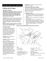
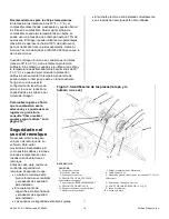
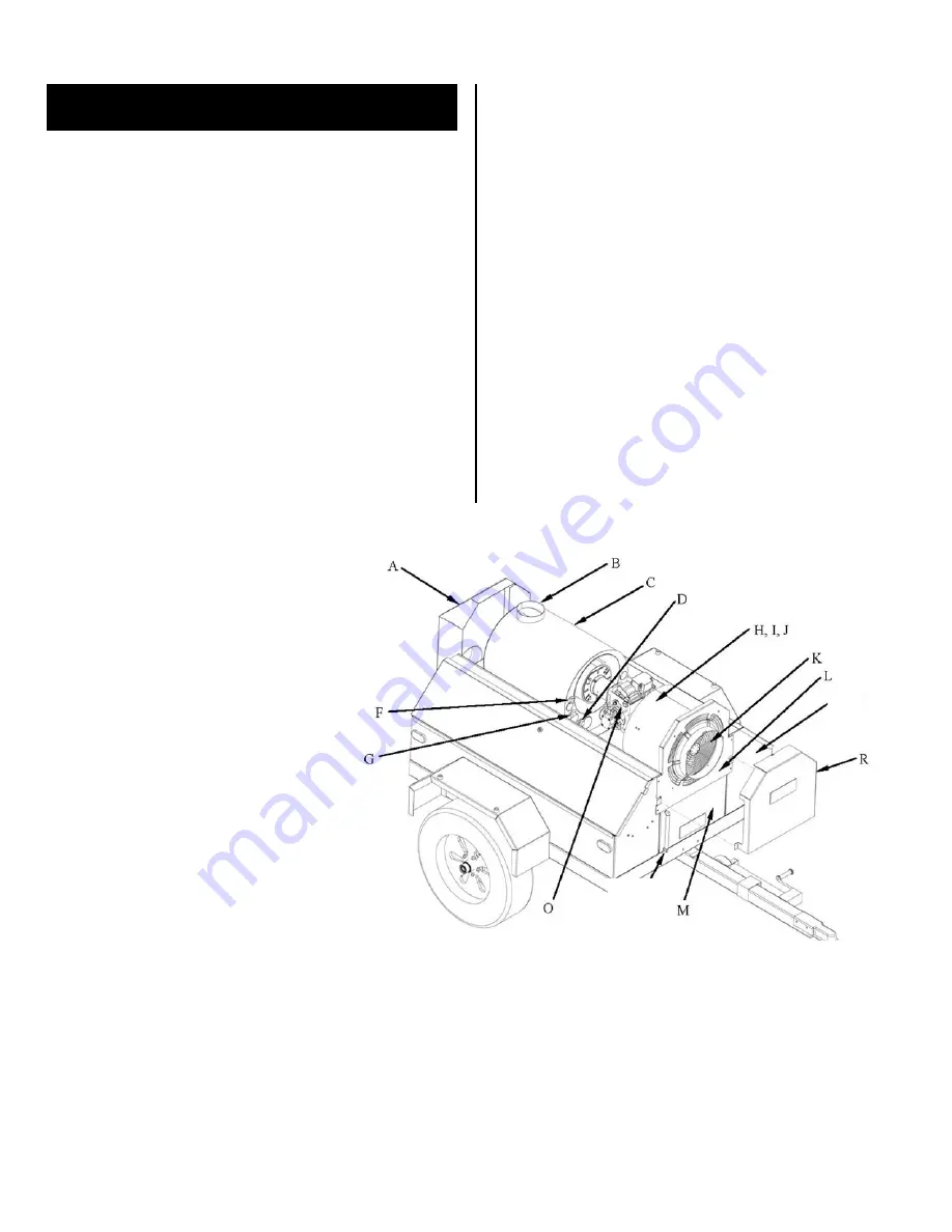
Figure 1: Parts Identification (hood and flue not shown)
KEY
A. Hot air outlets
J. Fan propeller (under shroud)
B. Flue connection
K. Inlet grill
C. Heat exchanger
L. Inlet duct ring (purchased separately:
part no. 13-01615)
D. HI-TEMP SWITCH manual reset
M. Fuel tank
F. COOL DOWN SWITCH
N. Fuel tank drain fitting
G. BURNER CONTROL SWITCH
O. AIR ADJUSTMENT SHUTTER (see Fig. 2)
H. Fan motor (under shroud)
P. Fuel gauge
I. Fan shroud
R. Rain Shield (customer installed)
N, P


