DRIESCHER
WEGBERG
26
LDTM-W 12 kV
-
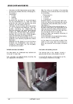
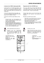
Kabelende nach Montageanweisung des Kabel-
garnituren-Herstellers absetzen und Kabelgarni-
tur montieren.
- Phasenfolge:
L1
links,
L2
Mitte,
L3
rechts!
-
Montieren Sie die Phase L1 und verschrauben
Sie das Kabelhalteeisen so, dass das Kabel
senkrecht nach unten ragt. Montieren Sie dann
Phase L2 und zum Schluss Phase L3.
-
Überprüfen Sie den Zustand der Endverschlüs-
se, z.B. Oberflächenbeschaffenheit, ordnungs-
gemäße Anordnung der Kabelschuhe und
Klemmverbindungen. Bei Kleinendverschlüssen
müssen die Klemmschrauben der Schlauch-
schellen nach vorn oder hinten angeordnet sein.
-
Beachten Sie die Sicherheits- und Montagehin-
weise des Herstellers der Kabelgarnituren!
-
Befestigen Sie die Endverschlüsse an den mit-
gelieferten oder bauseitig angebrachten Kabel-
halteeisen!
-
Befestigen Sie die Kabel so an den Anschluss-
kontakten des Schaltgerätes, dass keine me-
chanischen Spannungen auf die Kontaktan-
schlusslaschen einwirken!
-
Strip the cable end according to the assembly
instructions of the cable producer and assemble
the cable fitting.
-
Phase
sequence
L1 left hand,
L2
center,
L3 right hand!
-
Assemble phase L1 and screw the cable hold-
ing iron in a way that the cable extends vertical-
ly downwards. Now assemble phase L2 and fi-
nally phase L3.
-
Check the condition of the cable terminals, i.e.
the state of the surfaces, the right fixation of the
cable lugs and of the clamps. With small termi-
nals the clamping screws of the tube clips have
to be arranged in a front or a rear row.
-
Follow the safety and assembly instructions of
the cable producer!
-
Fix the terminals on the supplied cable holding
irons or the ones available at site!
-
Fix the cables to the connection contacts of the
switch in such a way that no mechanical ten-
sions are exercised on the contact connection
flaps!
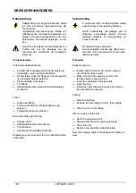
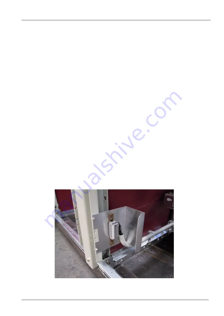
Hilfsstromkreise anschließen
Die Klemmleiste der Hilfsstromkreise befindet sich
hinter der Tür unten links.
Zum Anschluss der Hilfsstromkreise beachten Sie
die mitgelieferten Schaltpläne.
Connection of auxiliary circuits
The terminal strip of the auxiliary circuits is
placed behind the door at the bottom to the left.
To connect the auxiliary circuits please see the
circuit diagrams included in our supply.


