background image

DRIESCHER 

 WEGBERG


   2 

MINEX

®

-C


(DE-EN) 


Alle Rechte vorbehalten / All rights reserved 


DRIESCHER 

 WEGBERG 2018


Summary of Contents for MINEX-C

Page 1: ...bly Instructions Mittelspannungs Lastschaltanlage Typ MINEX C SF6 isoliert Bemessungsspannung bis 24 kV Bemessungsstrom 630 A Medium Voltage Switchgear Type MINEX C SF6 insulated Rated voltage up to 24 kV Rated current 630 A 03 2018 DRIESCHER WEGBERG ...

Page 2: ...DRIESCHER WEGBERG 2 MINEX C DE EN Alle Rechte vorbehalten All rights reserved DRIESCHER WEGBERG 2018 ...

Page 3: ... Betrieb 29 Operation 29 Inbetriebnahme 29 Setting to Work 29 Bedienung 30 Operation 30 Öffnen der Kabelraumabdeckung 30 Opening the Cable Compartment Cover 30 Schalten des Lasttrennschalters 31 Switching Switch Disconnector 31 Schalten des Erdungsschalters 33 Switching Earthing Switch 33 Austausch der HH Sicherungseinsätze 34 Replacement of HV HRC Fuses 34 Kabelprüfung und Kabelfehlerortung 36 Ca...

Page 4: ...switchgear Warnung vor einer Gefahrenstelle Warning of a danger area Warnung vor elektrischer Spannung Warning of electrical voltage Besondere Hinweise Special hints Diese Symbole finden Sie bei allen Hinweisen in dieser Betriebsanleitung bei denen Verletzungs oder Lebensgefahr besteht You will find these symbols with all hints given in this manual where risk of injury or danger of live exists Bea...

Page 5: ... proper and safe operation of the switchgear requires the following pre conditions Appropriate transport and correct storing Professional assembly and setting to work Accurate operation and maintenance through qualified personnel The observation of this manual The compliance with the regulations for instal lation operation and safety valid at site Another or an extended use is not regarded as in t...

Page 6: ...bsmitteln IEC 60376 Specification of technical grade sulphur hexafluoride SF6 for use in electrical equipment VDE 0671 Teil 1 Gemeinsame Bestimmungen für Hochspannungs Schaltgeräte Normen IEC 62271 1 Common specifications for high voltage switchgear and control gear standards VDE 0671 Teil 4 Handhabungsmethoden im Umgang mit Schwefelhexa fluorid SF6 und seinen Mischgasen IEC 62271 4 Handling proce...

Page 7: ...nen Daten und Hinwei se für die Installation Bedienung und Wartung der Schaltanlage entsprechen dem Stand der Druckle gung und erfolgen unter Berücksichtigung unserer bisherigen Erfahrungen und Erkenntnisse nach bes tem Wissen Liability limitations All technical information data and notes for the installation operation and maintenance of the medium voltage switchgear contained in these Operation a...

Page 8: ...ation Geben Sie bitte bei Rückfragen oder Ersatzteil bestellungen folgende auf dem Typenschild angege bene Daten an Stations Geräte Anlagentyp Auftragsnummer Fabrikationsnummer Baujahr Durch Angabe dieser Daten ist gewährleistet dass Ihnen die richtigen Informationen oder die benötigten Ersatzteile zugehen Fritz Driescher KG Spezialfabrik für Elektrizitätswerksbedarf GmbH Co Postfach 1193 41837 We...

Page 9: ...ne Zersetzungs erscheinungen bis 500 C Das Isoliergas wird werksseitig vor Auslieferung der Schaltanlage eingefüllt Der Bemessungswert des Fülldruckes beträgt 118kPa Der Berstdruck des Gaskessels wird durch definierte Berstscheiben auf 250kPa Überdruck limitiert Neben Kabel und Trafofeldern sind auch Leistungs schalter Mess und Übergabefelder lieferbar SF6 is a synthetic gas It is non flammable no...

Page 10: ...nment minimum pressure wave to the substation ABS im luftisolierten Messfeld Optimaler Personen Sach und Umweltschutz Minimale Druckwelle auf umgebende Stations bauteile ABS in the air insulated metering cubicle optimum protection of persons objects and environment minimum pressure wave to the substation Ein Drucksensor ist in die Gaskesselwand integriert und erfasst einen Druckanstieg aufgrund ei...

Page 11: ...ppe mit dem Verbotszeichen Berühren verboten gemäß DIN 4844 2 DGUV Vorschrift 9 versehen In order to avoid an improper activation of the anti burst system the sensor flap shows the prohibition sign to DIN 4844 2 DGUV standard 9 Do not touch Ein versehentliches Auslösen des DRIESCHER ABS durch den Bediener ist unter normalen Arbeitsbedingungen nicht möglich An unforeseen activation of the DRIESCHER...

Page 12: ...ltanlagenkombi nationen kann somit keine allgemeine Aussage zum Schaltanlagenraum und einer eventuell erforderli chen Druckentlastung getroffen werden Bei Fragen setzen sie sich mit unserem Kundendienst in Verbin dung The manual ON and OFF switching operation can be performed as usual under pre loaded energy storing device With the standard design switch disconnector and earthing switch are mechan...

Page 13: ...e voltage indicator according to the operating manual of the manufacturer with the measuring sockets and check if the switchgear is dead After the check Separate the voltage indicator from the measuring sockets Put the protective caps onto the measuring sockets to avoid the formation of dirt Keine Kurzschlussstecker verwenden Die Schutzfunktion der spannungsbegrenzen den Sollbruchstelle wird bei V...

Page 14: ... L 1 L1 L2 L2 L3 L3 of the corresponding cable ends with the phase comparison test device Check the phase parity Put the protective caps onto the measuring sock ets Benutzen Sie nur Prüfgeräte nach VDE 0682 Teil 415 für HR Systeme bzw LR systeme Beachten Sie die Betriebs anleitung der Prüfgerätehersteller und VDE 0682 Teil 415 Prüfen Sie die Prüfgeräte vor Gebrauch auf Funktion Please only use tes...

Page 15: ...ometer 12 Kurzschlussanzeiger Option 13 Galvanischer Zugriff hinter der Blende des Ka belanschlussraumes 14 Anzeige des Anti Berst Systems ABS 1 cable cubicle 2 transformer cubicle 3 fuse cover 4 cable connection area with cover 5 drive socket for switch disconnector 6 drive socket for earthing switch 7 measuring sockets for capacitive voltage measurement and phase comparison 8 name plate 9 label ...

Page 16: ...ribution line closed loop breaking current Bemessungs Kabelausschaltstrom 60 A Rated cable charging breaking current Bemessungs Freileitungsausschaltstrom 10 A Rated line charging breaking current Bemessungs Erdschlussausschaltstrom 300 A Rated earth fault breaking current Bemessungs Transformatorausschaltstrom 10 A Rated no load transformer breaking current Störlichtbogenqualifikation IAC AFL 20k...

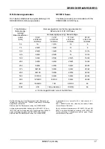
Page 17: ... fuse sizes are necessary Please contact Messrs Driescher Due to controversial statements in IEC 62271 105 and IEC 60787 no definite information according to IEC 62271 105 for the protection of transformers can be given Please contact Messrs Driescher Transformator Bemessungs leistung Rated transformer power kVA Bemessungsstrom des Sicherungseinsatzes A Rated current of HV HRC fuses Bemessungsspan...

Page 18: ...dausführung Kabel Kabel Trafo Ausführung 1700mm Dimensions and Weights Standard RMU version cable cable transformer design 1700mm Gewichte Kabelfeld ca 90kg Transformatorfeld ca 140kg Weights cable cubicle approx 90kg transformer cubicle approx 140kg DRIESCHER WEGBERG ...

Page 19: ...ables 12 to 17 5kV paper insulated cables with one or three conductors 24kV Nexans Gerader Stecker Typ 450 SR 12kV Typ K450 SR 24kV Mit Übergangs muffe anschließ bar Mit Übergangs muffe anschließbar Nexans Straight plug type 450 SR 12kV type K450 SR 24kV to be connected with transfer sleeve to be connected with transfer sleeve nkt cables Nordenham ehem F G Gerader Stecker Typ ASG1 10 400 Typ ASG1 ...

Page 20: ...ne or three conductor 12 to 24kV straight plug plastics or rubber insulated cables with one or three conductor 12 to 24kV elbow plug Nexans Typ 151SR oder 152SR 12kV Typ K151SR oder K152SR 24kV Typ AGG 250 Typ AGGL 20 250 Typ 158LR 12kV Typ K158LR 24kV Typ AGW 250 Typ AGWL 250 Nexans Type 151SR oder 152SR 12kV Type K151SR oder K152SR 24kV Type AGG 250 Type AGGL 20 250 Typ 158LR 12kV Typ K158LR 24k...

Page 21: ...transportiert werden darf Observe that the switchgear cannot be transported lying on the rear wall Verwenden Sie zum Heben und Transpor tieren der Schaltanlage Hebezeug Last aufnahmemittel und Anschlagmittel mit ausreichender Kraft Befestigen Sie An schlagmittel nur an den vorgesehenen Kranungsvorrichtungen For the lifting and the transport of the switchgear use lifting devices load absorp tion de...

Page 22: ...ft or lift truck The switchgear is top heavy Das zum Kranen erforderliche Maß X kann wie folgt ermittelt werden X Anzahl der Kabelfelder x 210mm Anzahl der Trans formatorfelder x 370 mm 70mm z B Anlage K K T X 2 x 210mm 1 x 370 mm 70 mm 720 mm Size X necessary for the craning can be calculated as follows X number of cable cubicles x 210 mm number of transformer cubicles x 370 mm 70 mm i e switchge...

Page 23: ... betragen die Schaltanlage nicht in explosionsgefährdeten oder staubexplosionsgefährdeten Räumen auf gestellt wird In case of walk in stations make sure that there is sufficient width between the corridors and the access areas for free movement and transport Minimum width of the operator passage 800mm The minimum width of the operator passage must be respected and shall not be narrowed by parts th...

Page 24: ...ection points in the cable compartment Bodenaussparung base recess Höhe der Schaltanlage height of the switchgear a b mm mm mm 1040 45 12 5 x 11 1300 1700 38 12 x 20 Aufstellungsempfehlungen Schaltanlagen Typ MINEX C sind mit einem ABS ausgerüstet das eine raumunabhängige Aufstellung ermöglicht Recommendations for the Installation Switchgears of type MINEX C are equipped with an ABS that enables a...

Page 25: ...partment covers see page 28 With a fixation directly into the concrete drill boreholes into the foundation and insert dowels Stellen Sie die Schaltanlage nur auf eben und waagerechte Betonfundamente oder auf Zwischenrahmen mit ausreichender Tragfestigkeit auf um ein Verspannen der Schaltfelder zu vermeiden Only install the switchgear on even and horizontal concrete foundations or interme diate fra...

Page 26: ... am anderen Ende erden und kurzschließen An der anzuschließenden Schaltanlage Lasttrennschalter ausschalten Erdungsschalter einschalten Abdeckblende nach vorne schwenken und geneigt abnehmen Entsprechendes Kabelende aus dem Ka belkanal oder Kabel Zwischenboden in den Kabelanschlussraum führen Kabelende nach Montageanleitung des Ka belgarnituren Herstellers absetzen und Ka belgarnitur montieren Pha...

Page 27: ... the cable with suita ble cable clamps onto the cable holding iron in such a way that the cable extends vertically downwards Then assemble phase L2 and finally phase L1 Check the state of the terminals i e the state of the surfaces the right location of the cable lugs sockets and the clamps Earth the cable shields at the earthing screws of the cable holding iron Respect the safety and assembly ins...

Page 28: ...gefahr Bleche nicht verbiegen Pay attention to the switch position indica tion sheets of the operating mechanism Danger of injuries Do not bend the sheets Schrauben Sie die Frontblende des zweiten Kabelschaltfeldes von links ab Die externen Zuleitungen an die Klemmleiste heranführen Leitungen gemäß den Schaltplänen an schließen und sauber verlegen Polung beachten Hilfsspannung noch nicht einschalt...

Page 29: ... switched on Kontrollieren Sie die HH Sicherungseinsätze siehe Kapitel Austausch der HH Sicherungseinsätze Sonstige Kontrollen Prüfen Sie die Zusatzeinrichtungen falls vor handen Anschlussbuchsen für kapazitive Span nungsanzeigegeräte müssen während des Betriebes mit Abdeckstopfen oder Anzeige geräten ausgerüstet sein Kurzschlussanzeiger zurückstellen Funktion des Motorantriebes bei Last trennscha...

Page 30: ...lende nicht wie der einschalten Einsetzen der Blende Setzen Sie die Kabelraumblende nach vorn ge neigt mit den unteren Rastnocken in die entspre chenden Schlitze im unteren Querholm Schwenken Sie die Kabelraumblende an die Schaltanlage und schließen die Schnellver schlussschrauben mit der Schaltkurbel Removal of the cover Untie the quick release screws with the switch crank inside hexagonal recess...

Page 31: ...ned during making operation The free tripping is performed by means of HV HRC fuses with striker pin of the medium class according to IEC 60282 1 by means of a trip coil option As an option the free tripping of the switch disconnector can be deactivated by means of the striker pins of the HV HRC fuses For disassembly of the relevant components see Appendix A Actuation Put the switch crank with the...

Page 32: ...ivieren Stecken Sie die Schaltkurbel in die Antriebs buchse des Lasttrennschalters Drehen Sie die Schaltkurbel gegen den Uhrzei gersinn bis zum hörbaren Einrasten in die End stellung Der Schalter ist einschaltbereit Safeguarding against reclosing Apply the mechanism cover with warning plate optional onto holding point and cover the mecha nism opening Re activate the transformer switch disconnector...

Page 33: ... Der Erdungsschalter lässt sich nur bei aus geschaltetem Lasttrennschalter schalten The earthing switch can only be switched provided the switch disconnector is in OFF position Erdungsschalter einschalten Drehen Sie die Schaltkurbel zügig im Uhrzei gersinn Schalterstellungsanzeiger senkrecht Erdungsschalter ausschalten Drehen Sie die Schaltkurbel zügig gegen den Uhrzeigersinn Schalterstellungsanze...

Page 34: ...IEC 60282 1 see recommendations for fuse protection on page 15 Due to the fact that the HV HRC fuses are accommodated in a fuse tube the power loss of 100W per phase may not be exceeded related to the operating current value at 40 C The tripping of a HV HRC fuse is shown by a horizontal bar at the switch position indicator that is situated in the fuse cover We recommend to replace all fuses even i...

Page 35: ... zum Anschlag in den Sicherungshalter stecken Pull out the fuse holder and support the fuse with the other hand at same time Unscrew the screws with the hexagonal wrench 5mm For this use the hexagonal wrench available next to the quick release lock Remove the fuse from the fuse holder Insert a new fuse into the fuse holder until it clicks in Das Einsetzen des Sicherungshalters ist leicht möglich K...

Page 36: ...rüfen Prüfstifte mit beschädigter Isolierung nicht benutzen sondern austauschen Check the insulation of the test pins 2 for damage i e cracks Do not use test pins with damaged insulation but replace these Prüfstifte reinigen trocknen und die Gummi buchsen an der Dichtfläche mit Montagegleit paste einreiben Prüfstifte in den galvanischen Zugriff einführen und handfest verschrauben L1 kurzer Prüfsti...

Page 37: ...ism with gear is installed behind the front cover of the cubicles It actuates the drive shaft by means of a chain wheel drive and operates the switch ON and OFF The switching angle for the ON OFF switching of the switch disconnector is predetermined in the factory The motor mechanism is designed for direct current supply For the operation with alternating current a rectifier has to be used Technic...

Page 38: ...Motorantrie bes am jeweiligen Schaltfeld Die Schaltvorgänge erfolgen dann wie bei einem handbetätigten Schalter Emergency Unlocking In case of a fault resp breakdown of the auxiliary supply of the motor mechanism the switch can be manually actuated with the crank For this purpose the gear of the motor mechanism first has to be unlocked You unlock the gear by extracting the unlocking bolt 1 and tur...

Page 39: ...eim Ausschalten des Lasttrennschalters öffnet Bei DC Anwendung werden zusätzlich ein Hilfs schalter und ein Entstörkondensator verwendet Trip coil option The trip coil auxiliary coil is not designed for 100 ON time so always shut OFF the circuit via the auxiliary switch With AC 110 230V one auxiliary switch is used for the interruption which opens if the switch is switched OFF With DC applications...

Page 40: ...es Short circuit indicators integrated into the front cover Short circuit indicators directly mounted on the single core cables cable compartment covers with an inspection window are necessary Erdschlussanzeiger Option Optional kann die Schaltanlage mit Erdschlussan zeigern ausgerüstet werden Es gibt zwei Möglichkeiten In die Frontblende integrierte Erdschlussanzei ger Kombinationen aus Kurzschlus...

Page 41: ...de Instandhal tungsarten zu unterscheiden vorbeugende Instandhaltung ereignisorientierte Instandhaltung zustandsorientierte Instandhaltung prioritätenorientierte Instandhaltung Nach Kapitel 5 Abschnitt 5 1 o g Norm ist der Netzbetreiber dafür verantwortlich die Instandhal tung und Instandhaltungsunterstützung zu planen und zu entwickeln Dabei werden die Grundsätze für die Planung der Instandhaltun...

Page 42: ...er and serial number of the switchgear nameplate Exact designation of the component or device Entsorgung Die SF6 isolierten Schaltanlagen Typ MINEX C sind umweltverträgliche Erzeugnisse Die Materialien der Anlagen sollten möglichst recy celt werden Die Entsorgung der Anlagen ist auf der Grundlage der bestehenden Rechtsvorschriften um weltschonend möglich Die Bestandteile der Schaltanlage sind als ...

Page 43: ...elektrotechnischen Regeln vorgegebenen Grenzwerte Beachten Sie die Herstellerbedingungen für Span nungsanzeigegeräte Dangerous substances do not exist Regarding the disposal of SF6 gas please follow the notes on page 45 Testing the Switchgear Check the proper state of the switchgear before the first start after a modification or maintenance of the switchgear at least every 4 years DGUV standard 3 ...

Page 44: ...hgear can be equipped with a manometer or a declared spark gap Manometer Die Prüfung des Isoliergasdruckes erfolgt über die Rot Grün Anzeige des eingebauten Manometers Die Anzeige des Isoliergasdruckes erfolgt abhängig von der Anlagentemperatur Manometer The check of the insulating gas pressure is done by a red green display on the incorporated ma nometer The display of the insulating gas pressure...

Page 45: ... kann bei in Betrieb befindlicher Anlage durchgeführt werden Bei Einbau einer Soll funkenstrecke entfällt das Manometer Declared Spark Gap Option The quality of the insulating gas can be checked via a declared spark gap check of the electric strength of the SF6 For this purpose the piezo insulating gas test de vice type PI45 operating without a battery is used Remove the cap of the spark gap spark...

Page 46: ...ter lässt sich nicht einschalten Freiauslösung des Transforma tor Lasttrenn schalters erfolgte durch HH Sicherungsein sätze mit Schlagstift oder durch Magnet auslöser Lasttrennschalter Schaltkurbel gegen den Uhr zeigersinn in die Endstellung drehen An schließend ist der Transformator Lasttrennschalter einschaltbereit 3 Transformer switch disconnector cannot be switched ON The trip free mechanism o...

Page 47: ...e Sicherungsabdeckblende ab Entfernen Sie die Frontblende wie in Anhang B beschrieben Entfernen Sie den Befestigungsclip und an schließend den Haltebolzen und den Auslösehe bel Legen Sie die Bauteile für eine spätere Wieder aktivierung zum Anlagenzubehör Montieren Sie die Frontblende unter Beachtung der Montagehinweise in Anhang B Nehmen Sie die Schaltanlage wieder in Betrieb Aktivierung der Siche...

Page 48: ...m Unscrew the fixing screws of the front cover and remove same Assembly of front cover at transformer cubicles For the installation of the front cover 1 slide the locking sheet 2 inside the cover upwards Montieren Sie die Frontblende mit den Befesti gungsschrauben Verbinden Sie den oberen 3 und den unteren 4 Teil des Verriegelungsgestänges indem Sie die Rückwärtsverriegelung 5 soweit betätigen bis...

Page 49: ...sen Wartungsgerät benut zen nach dem Anschließen Verbindungen auf Dichtigkeit prüfen Verunreinigtes SF6 nur in gekennzeichnete SF6 Druckgasbe hälter füllen Anlagen mit verunreinigtem SF6 24 Stunden in 3 Sodalö sung Neutralisationsbehälter tauchen Filling Emptying or Evacuating the SF6 switchgears Check the state of SF6 i e humidity air portion pollution Do not bring out SF6 into the atmosphere use...

Page 50: ...Français Contient des gaz à effet de serre fluorés HU Magyar Fluortartalmú üvegházhatású gázokat tartalmaz ΙΤ Italiano Contiene gas fluorurati ad effetto serra IRL Irih Tá gáis cheaptha teasa fhluairínithe HK Hrvatski Sadrži fluorirane stakleničke plinove LT Latviešu Sudėtyje fluorintų šiltnamio efektą sukeliančių dujų LV Lietuvių Satur fluorētas siltumnīcefekta gāzes MT Malti Fih gassijiet serra ...

Reviews: