User Manual Nitro
5
Drive Medical GmbH & Co. KG | As per: 12.03.2018 | Subject to error and change
EN
Indication / Contraindication
This walking aid is suitable for a single user with limited
mobility. It is suitable for indoor and outdoor use.
The purpose of walking devices is to compensate for or
at least improve restricted walking ability in users (ex-
pansion of range and/or mobility).
Persons with restricted hand/arm functions require spe-
cial adjustments/versions of handgrips or hand rests/
armrests.
For persons with balance disorders are walking frames
not recommended, this is to be checked by an experi-
ment in an individual case. if it is necessary a compa-
nion must be present.
Sope of delivery contents
1. Rollator Nitro
2. Bag
3. Back Rest
4. Cane Holder
5. Operating instructions
Indikati Lieferumfang
Unfolding
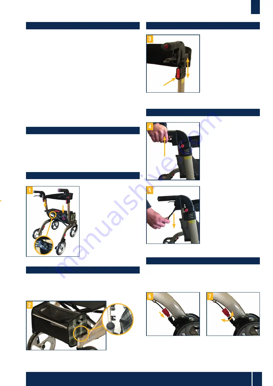
Position the Rollator on its
wheels. Open the Rollator.
Press the tubes attached
to the seat downwards
until they lock into positi-
on. (picture 1)
The rollator is correctly
unfold when the locking
hook is engaged.
Removing / Attaching the Carry Bag
To attach the bag, fold the Rollator a little and push the
sliding block from bag into guiding part on the Rollator,
unfold the Rollator – ready. (picture 2).
Hight adjustment handgrips
Press and hold down the
red release buttons as
shown in picture 3.
Simultaneously move the
handgrip up or down.
When the desired height
is reached, let go of the
red release buttons and
the handgrip will automa-
tically lock into the next
possible height position.
Breaking / Parking
Pull both brake levers up-
wards to apply the bra-
kes whilst the rollator is
moving (see picture 4).
Always brake slowly and
steady.
To lock the brakes, ensu-
re the Rollator is stationa-
ry and press both brake
levers down until they
lock into position (see
picture 5).
To release the brakes
from the locked position,
pull up on the brake
levers.
The effect of the brakes
can be affected by abra-
sion of the wheels. There-
fore regularly test the
brakes.
Adjustment of brakes
To adjust the braking strength, adjust the brake by pres-
sing the screw housing downwards (picture 6)
and then turn left or right (picture 7).


