14
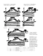
Fig. 3.4a Grounding of Multiple inverters.
Good
Good
Bad
3.4 Grounding
Connect positive earth ground using terminal E on the Main Circuit terminal (TM1).
CAUTION:
Ground wire size should be in accordance with NEC regulations or at least 14 AWG minimum. The lead
length should be kept as short as possible.
NOTE:
Ground resistance to building earth should be below 100 ohm. Provide extra ground collector shoe if unsure
of ground on crane itself.
NOTE:
NEVER
ground inverter along with welding machines, large current motors....etc.
NOTE:
Where several inverter units are used together all of them should be directly grounded to a common point.
Please follow the grounding instructions shown in Fig. 3.4.
WARNING:
Never ground or connect terminal N of inverter to neutral.
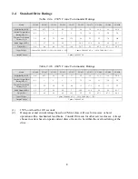
Table 3.3b CC-4XX Series
Inverter type
CC-407
CC-415
CC-422
CC-437
CC-455
CC-475
CC-4110
CC-4150
CC-4220
MCCB / fuse rating
10A
15A
20A
30A
40A
50A
75A
MC (A/B IEC rated)
100A09ND3
100A12ND3
100A18ND3
100A30ND3
100A38ND3
100A45ND3
Wire Size *1
(minimum)
TM1
14 AWG
12 AWG
10 AWG
8 AWG
4 AWG
TM2/TB1
18 AWG
Screw *2
Terminal size
TM1 (torque)
M4 (16 in.-lbs)
M6 (22 in.-lbs.)
TM2 (torque)
M3 (7 in. - lbs.)
TB1 (torque)
Wire clamp type captive screw. (10 in. - lbs.)
NOTE:
*1 Use copper conductors only, minimum size listed, size field wiring based on 75°C wire only.
*2 Use only U.L. listed field wiring lug kits or U.L. listed ring terminals.


