


3
Technical Specifications for:
PWRM212S, PWRM212D, PWRM214S, PWRM214D, PWRM216S and
PWRM246S, PWRM246D, PWRM248S, PWRM248D, PWRM2410S, PWRM2410D
Receiver input voltage
: 110 volts AC.
Other Input voltages available 220 VAC, 12V AC/DC, 24 VAC/DC
Temperature
: -35 deg C to 75 deg C (-31 deg F to 167 deg F)
Receiver relay ratings
: the receiver relays are rated at 10 amps at 250 volts AC. All COM wires are
fused at 10A in both the PWRM21 and PWRM24 series.
The total current drawn through the receiver
relays (through the COM wire) must not exceed 10A.
Transmitter weights:
5 ounces for PWRM21-2S, 2D; 9 ounces for PWRM21-4S, 4D, 6S; 11 ounces for
PWRM24-6S, 6D, 8S, 8D, 10S, 10D
Transmitter dimensions:
PWRM21-2S, 2D are 5.2” x 1.75” x .9”; PWRM21-4S, 4D, 6S are 6.2” x 2.4”
x 2”; PWRM24-6S, 6D, 8S, 8D, 10S, 10D are 7.25” x 2.4” x 2”
Frequency generation:
Crystal (plug-in)
Transmitter and Receiver housing material
: 30% glass fiber-reinforced nylon-6
Transmitter button life
: Tested to 2,000,000 operations
Control range
: 150 feet for PWRM21-2 button models, 250 feet for PWRM21-4 & PWRM21-6 button
models and 500+ feet for all PWRM24 models.
Transmitter batteries
: 2 AA alkaline batteries.
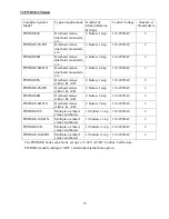
Channel Frequency Channel Frequency Channel Frequency Channel Frequency
1
310.0325
11
312.7075
21
315.3825
31
318.0575
2
310.3000
12
312.9750
22
315.6500
32
318.3250
3
310.5675
13
313.2425
23
315.9175
33
318.5925
4
310.8350
14
313.5100
24
316.1850
34
318.8600
5
311.1025
15
313.7775
25
316.4525
35
319.1275
6
311.3700
16
314.0450
26
316.7200
36
319.3950
7
311.6375
17
314.3125
27
316.9875
37
319.6625
8
311.9050
18
314.5800
28
317.2550
38
319.9300
9
312.1725
19
314.8475
29
317.5225
10
312.4400
20
315.1150
30
317.7900
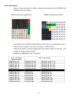
Channel Frequency Channel Frequency Channel Frequency Channel Frequency
112
428.5350
123
431.4775
134
434.4200
145
437.3625
113
428.8025
124
431.7450
135
434.6875
146
437.6300
114
429.0700
125
432.0125
136
434.9550
147
437.8975
115
429.3375
126
432.2800
137
435.2225
148
438.1650
116
429.6050
127
432.5475
138
435.4900
149
438.4325
117
429.8725
128
432.8150
139
435.7575
118
430.1400
129
433.0825
140
436.0250
119
430.4075
130
433.3500
141
436.2925
120
430.6750
131
433.6175
142
436.5600
121
430.9425
132
433.8850
143
436.8275
122
431.2100
133
434.1525
144
437.0950
Summary of Contents for PWR MICRO PWRM212D
Page 2: ......
Page 4: ...2 This Page Intentionally Left Blank ...
Page 20: ...This page intentionally left blank ...
Page 22: ...This page intentionally left blank ...
Page 24: ...This page intentionally left blank ...
Page 26: ...This page intentionally left blank ...
Page 28: ...This page intentionally left blank ...
Page 30: ...This page intentionally left blank ...
Page 32: ...This page intentionally left blank ...
Page 34: ...This page intentionally left blank ...
Page 36: ...This page intentionally left blank ...
Page 38: ...This page intentionally left blank ...
Page 40: ...This page intentionally left blank ...
Page 42: ...This page intentionally left blank ...
Page 43: ......


