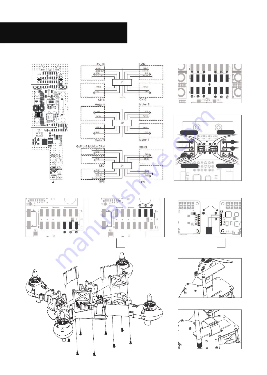
No.2 ESC
No.1 ESC
No.3 ESC
No.4 ESC
No.2 ESC
No.1 ESC
No.3 ESC
No.4 ESC
-
-
-
-
-
+
Connection Diagram
- 5 -
300 Main PCB Board
<
>
<
>
Connector wiring diagram
J1
J2
J4
USB external port
ESC Connector J2
<
>
/
J4 : PPM Setup
<
>
J4 : S-BUS Setup
<
>
Side Cover
M3 x 8mm
Tapping Bolt
LOPL45
Attach non-slip pad for battery
to Main Roof Panel.
Tie up Velcro Battery Straps using holes.
GPS Remove Module
Serial system receiver and GPS cannot be used at the same time.
-
+
P
DSMx SUMD
<
>
/
FC top view
FC
Bottom view
Soldering


