30
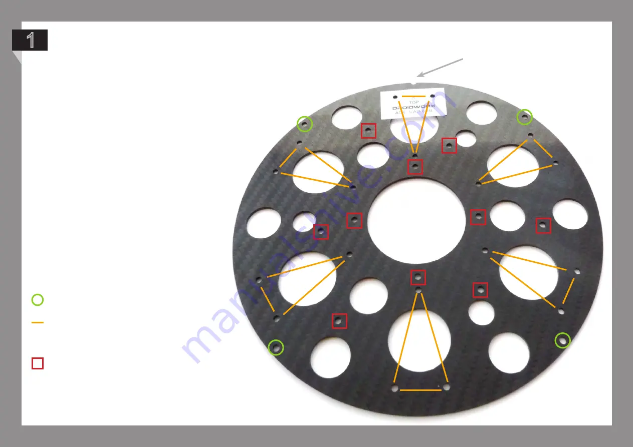
Squares represent the remaining holes
you can attach the standoffs to. This is all
dependent on which electronics you will
be using. In this guide we will demonstrate
how to attach the Universal Adapter Plate
we send with all of our crafts.
The notch indicates the front of the craft.
Take a moment to familiarise yourself
with the centre plate setup to get an
understanding which holes relates to
which parts. Take one of the plates
and lay it out with the notch at the top
and the sticker facing up.
Circles show the holes used
for dome fixing.
Lines indicate the boom mount triangle
pattern used for all models.
1
NOTE: It is important that you install
the standoffs for your electronics
BEFORE mounting the booms as you
will not be able to reach the required
holes afterwards.
Summary of Contents for VM 6
Page 1: ...1 S e r i e s B u i l d M a n u a l D r o i d w o r x L t d N e w Z e a l a n d...
Page 3: ...3 F l i g h t o p e r a t i o n a n d s a f e t y...
Page 8: ...8 A ss e mb l y o v e r v i e w...
Page 10: ...10 A ss e mb l y I n s t r u c t i o n s...
Page 11: ...11 Part 1 Landing Gear Assembly...
Page 21: ...21 Your final setup should now look like this 12...
Page 22: ...21 P a r t 2 C e n t e r P l a t e a n d B o o m A ss e mb l y i n s t r u c t i o n s...
Page 29: ...28 Your setup should now look like this 12...
Page 32: ...31 To build the VM6 core is exactly the same as the VM4 except there are no spacers required 2...
Page 35: ...34 To build the VM8 core is exactly the same as the VM4 except there are no spacers required 2...
Page 37: ...36 P a r t 4 E n g i n e M o u n t A ss e mb l y...


