DRS Firmware Manual v2.6-EN (2022-07-19)
©2022 Drone Rescue Systems GmbH
7/19
POWER_MONITOR
0: no deployment on power loss
1: deploy on power loss when when the system is in automatic state (Caution:
opening the bayonet mount of the DRS container disconnects the power supply
which is interpreted as a power loss, thus causes a deployment if the system is
in automatic state!)
Recommended: 1
Range: 0, 1
Resolution: -
Unit: -
MANUAL_DEPLOY_INPUT
0: PWM signals are not used
1: PWM input 1 is used to trigger deployment
2: PWM input 2 is used to trigger deployment
3: a trigger signal must be sent on both PWM inputs to deploy the parachute
4: a trigger signal can be sent on either PWM input to deploy the parachute
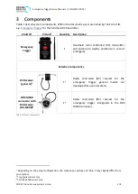
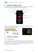
5: an SBUS signal on PWM input 2 is used to deploy the parachute (used by the
Emergency Trigger Device)
Recommended: -
Range: 0 - 5
Resolution: -
Unit: -
INTERFACE
The interfaces are explained in chapter 6.
0: logic motor enable signal
1: PWM motor enable signal
2:
reserved for future use
3: DJI-API (Onboard SDK)
4: MAVLink (UART)
Recommended: -
Range: 0 - 4
Resolution: -
Unit: -
UART_BAUDRATE
This baudrate is used for the UART connection of the specified
. It applies
to DJI-API and MAVLink. The DJI-API usually uses 115200, MAVLink usually uses
57600 baud. The baudrate must match the setting of the flight controller (see the
parachute manual for setup instructions).
Recommended: -
Range: 19200 - 3500000 Resolution: 1
Unit: baud
GNSS_MODE
The GNSS feature is only available on DRS variants with GNSS support. GNSS_MODE
must be set to 0 on standard variants.
0: GNSS disabled
1: GNSS enabled, data recording only
2: GNSS enabled, geofence enabled (geofence file has to be provided)
Recommended: -
Range: 0 - 2
Resolution: -
Unit: -
GNSS_TIMEOUT_DEPLOY
If GNSS is enabled and geofence is used, the parachute deploys when GNSS signal is
lost for this period given in seconds. Set to zero to disable this feature.
Recommended: 0
Range: 0 - 600
Resolution: 1
Unit: s

