DRS Firmware Manual v2.6-EN (2022-07-19)
©2022 Drone Rescue Systems GmbH
14/19
6
Interface description
The interface allows a communication between the DRS and the flight controller or any other
computer which controls the UAV. Diverse data and events can be propagated depending on
the interface type. The type of interface is selected with the configuration parameter
Logic Motor Enable Signal
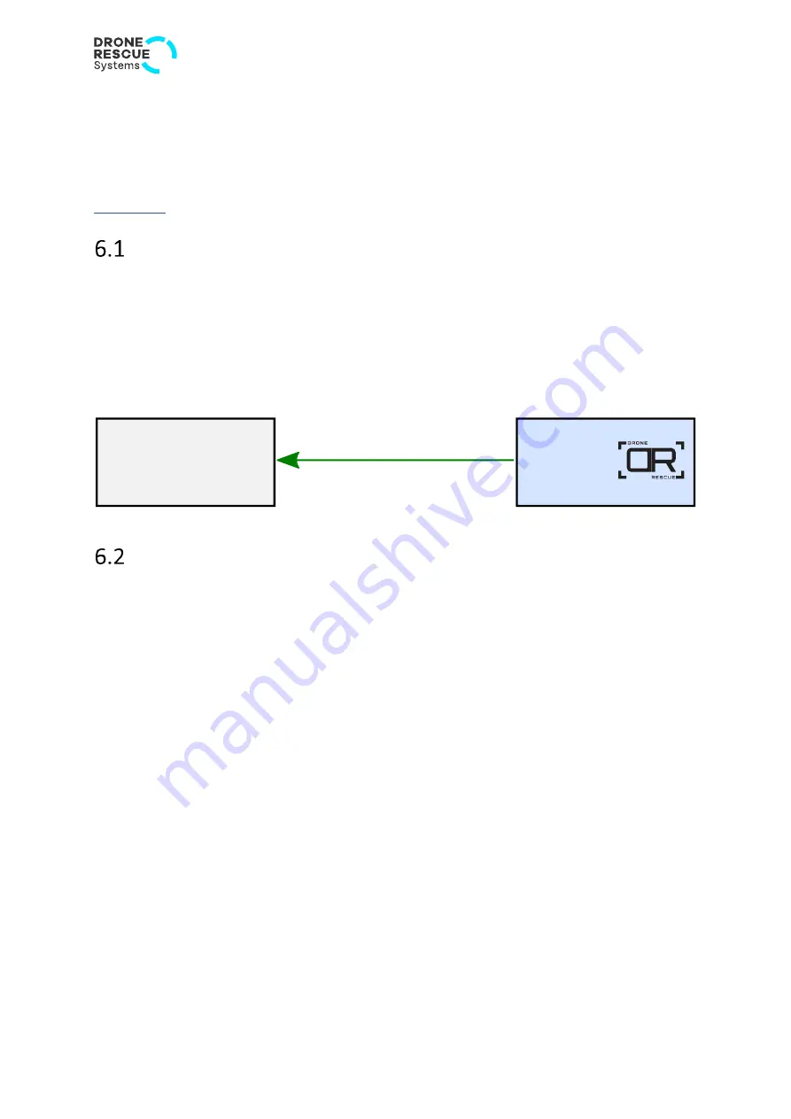
This is a very simple interface with only one piece of information to be transferred
–
the motor
enable signal. Whenever the DRS decides to deploy the parachute (also in the case of a manual
deployment), it informs the flight controller about it so it can stop the motors.
A 3.3V-CMOS voltage level is used for signaling the need to stop the motors. A logic low level
indicates normal operation (i.e., motors on) while a logic high indicates to stop the motors.
PWM Motor Enable Signal
This is a very simple interface with only one piece of information to be transferred
–
the motor
enable signal. Whenever the DRS decides to deploy the parachute (also in the case of a manual
deployment), it informs the flight controller about it so it can stop the motors.
A PWM signal is used to tell the flight controller to stop the motors. The general specifications
are taken from a conventional servo signal (50 Hz PWM signal with a pulse width between
1 ms and 2 ms, 3.3V-CMOS voltage levels). The following pulse widths are generated by the
DRS:
•
1.05 ms: Motors ON (normal operation)
•
1.95 ms: Motors OFF (request to stop the motors)
These pulse widths should be appropriate for most RC receivers, but keep in mind that they
will deviate somewhat due to clock frequency errors of the sender as well as the receiver of
the PWM signal.

