background image


DOC-0341 Rev E 

© 2019 DROPLET MEASUREMENT TECHNOLOGIES LLC


6  

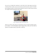
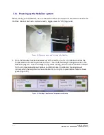
Once  you  have  connected  the  compressed  air  to  the  APEX  2Q  (via  a  filter  between  tank  and  an 

included mass flow controller), all you need to do is (1) connect the mass flow controller to the COM 

port on the back of the SP2-D, and (2) connect the APEX 2Q to the inlet of the SP2 using a plumbing 

“T

ee

” 

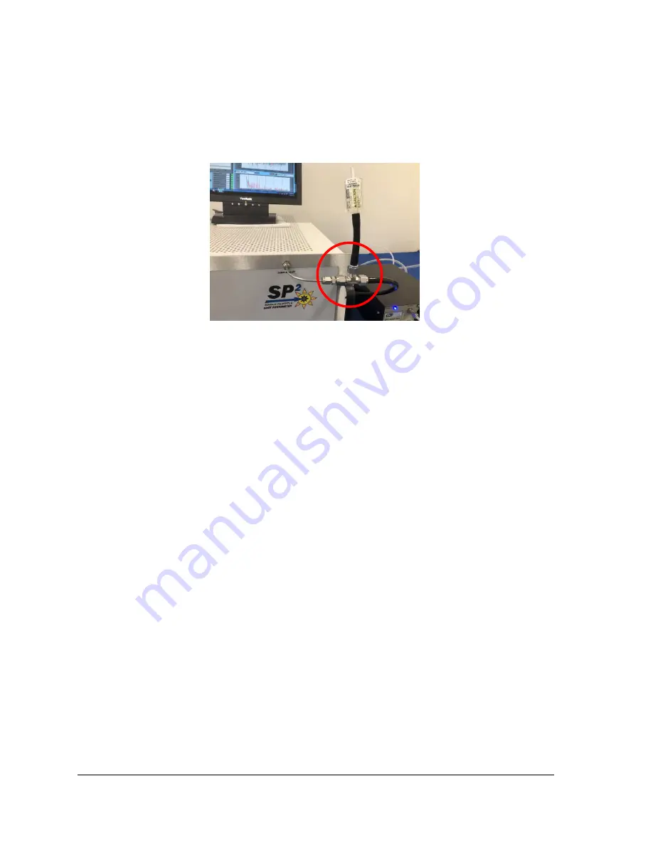
(Figure 2) and then you will be up and running. 


Figure 1: Plumbing Tee connection from Nebulizer to SP2 

While you are setting up the system, you should have two reference documents available and close 

by  for  reference:    1)  The  SP2  Operators  Manual  (included  with  your  SP2),  and  2)  the  APEX  2Q 

Operation and Installation Guide (included with your APEX 2Q). 


Summary of Contents for APEX 2Q

Page 1: ...Setup Guide for the SP2 with APEX 2Q Nebulizer 2400 Trade Centre Avenue Longmont CO 80503 USA DOC 0341 Revision E A L L R I G H T S R E S E R V E D...

Page 2: ...ction 7 Part 1 Unpacking Setup Installation and Power Up 8 1 6 Contents 8 SP2 Set up 10 Nebulizer Set up 11 1 7 APEX 2Q Nebulizer used with the SP2 Refer to APEX 2Q Manual 11 Mass Flow Controller Set...

Page 3: ...w Control 13 Figure 10 ZERO filter attached 14 Figure 11 SP2 Program launch Icon 14 Figure 12 Config Tab and Program Subtab 15 Figure 13 Plug in the Alicat controller and verify flow 15 Figure 14 Enab...

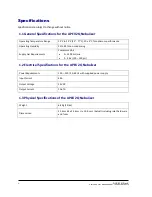
Page 4: ...Operating Humidity 35 to 85 non condensing Supply Gas Requirements Compressed Air 0 1200 mL min 2 9 bar 29 130 psi 1 2 Electrical Specifications for the APEX 2Q Nebulizer Power Requirements 100 240 50...

Page 5: ...nformation Please refer to the APEX 2Q Nebulizer section 1 for all safety information associated with that product 1 5 Brief Theory of Operation To measure a sample using the Single Particle Soot Phot...

Page 6: ...OM port on the back of the SP2 D and 2 connect the APEX 2Q to the inlet of the SP2 using a plumbing Tee Figure 2 and then you will be up and running Figure 1 Plumbing Tee connection from Nebulizer to...

Page 7: ...l resolution The SP2 is the ideal alternative to these traditional techniques It requires very little sample volume resulting in high time resolution Furthermore the SP2 will measure both black carbon...

Page 8: ...bing needed to run the APEX 2Q nebulizer with your SP2 D Check for documentation as well DMT provides this setup guide and the APEX 2Q Nebulizer comes with its own Installation and Operating Guide alo...

Page 9: ...in components of the system including the Nebulizer Alicat flow controller required tubing and Operator Manuals Unpack carefully and alert DMT Immediately of any damage that might have occurred during...

Page 10: ...perator Manual that was shipped with the instrument In addition to mitigate the risk of contamination of the optical cavity of the SP2 by unfiltered air while the instrument is not running and or in t...

Page 11: ...de Figure 6 1 2 Connect the Poly tubing from the Alicat OUT port to the inline filter Figure 6 2 3 Connect the power supply for the Alicat flow controller figure 6 3 Figure 6 Connecting the Mass Flow...

Page 12: ...e Manager Tab 1 Make sure the Alicat control cable is connected to the SP2 on the back panel of the unit 2 Open Windows Device Manager Figure 7 3 Look for the list of devices and COM ports Figure 7 If...

Page 13: ...play it should say 9 If the setpoint did not change plug in to the other COM port and verify that the Alicat is connected correctly 6 Once the COM port is verified change the flow on the Alicat flow c...

Page 14: ...nd let it run for some time before the laser is activated Once the system is warmed up and working properly you can replace the nebulizer cover and secure it using the two back panel screws SP2 and Ne...

Page 15: ...rect file is loaded 8 If a different file is listed press the Load a File button Figure 12 Navigate to the directory C DMT SP2 Support Select the SP2 Configuration ini and click OK 9 Next make sure th...

Page 16: ...urn ON the Sample Pump in the SP2 software Figure 15 You should hear the pump start Do Not turn on the Laser until you complete the following steps Figure 15 Turn on the SP2 Pump 13 Make sure the flow...

Page 17: ...41 Rev E 1 7 2019 DROPLET MEASUREMENT TECHNOLOGIES LLC 15 The SP2 should be allowed to warm up and stabilize for about 20 minutes while sampling the filtered air Figure 17 Figure 17 Sample Flow Stabil...

Page 18: ...er 1 Once the Nebulizer has been powered up let the machine run for 5 10 minutes to allow the temperature controllers to pre heat and cool Then start the Omega UI program which is the Nebulizer progra...

Page 19: ...EMENT TECHNOLOGIES LLC 2 Make sure that both the SP2 pump and laser are powered on Once verified click on the Control tab in the SP2 software Figure 20 Figure 20 Turning on the Laser from the Control...

Page 20: ...DOC 0341 Rev E 2019 DROPLET MEASUREMENT TECHNOLOGIES LLC 2 0 4 Go to the SP2 tab in the software and verify the particle response Figure 21 Figure 21 Verifying Particle Response...

Page 21: ...ow and is not connected to any other components 7 Check to be sure that the incandescence and scattering concentrations are near zero If they are not near a zero concentration there is a possibility o...

Page 22: ...er and is clear and dry for the next use Figure 25 Remove sample tube from sample container 3 Shut down the APEX 2Q software by closing the Omega UI 4 Turn off the APEX 2Q using the System Power switc...

Page 23: ...gies to be your Global Choice for Atmospheric Environmental Measurement Solutions and your Trusted Partner for Scientific Exploration Should you have any additional questions or comments please contac...

Page 24: ...er will pay for shipping to DMT while DMT will pay for the return shipping expense Consumable components such as tubing filters pump diaphragms and Nafion humidifiers and dehumidifiers are not covered...

Reviews: