background image

DOC-0128 Rev F 

© 2017 DROPLET MEASUREMENT TECHNOLOGIES 

1 8  

2.0


Installation  

The CCN-200 is designed for ground-based or airborne applications. The entire sampling system is 
sealed on the CCN-200 so that it can be used on a pressurized aircraft as long as the sample air inlet 
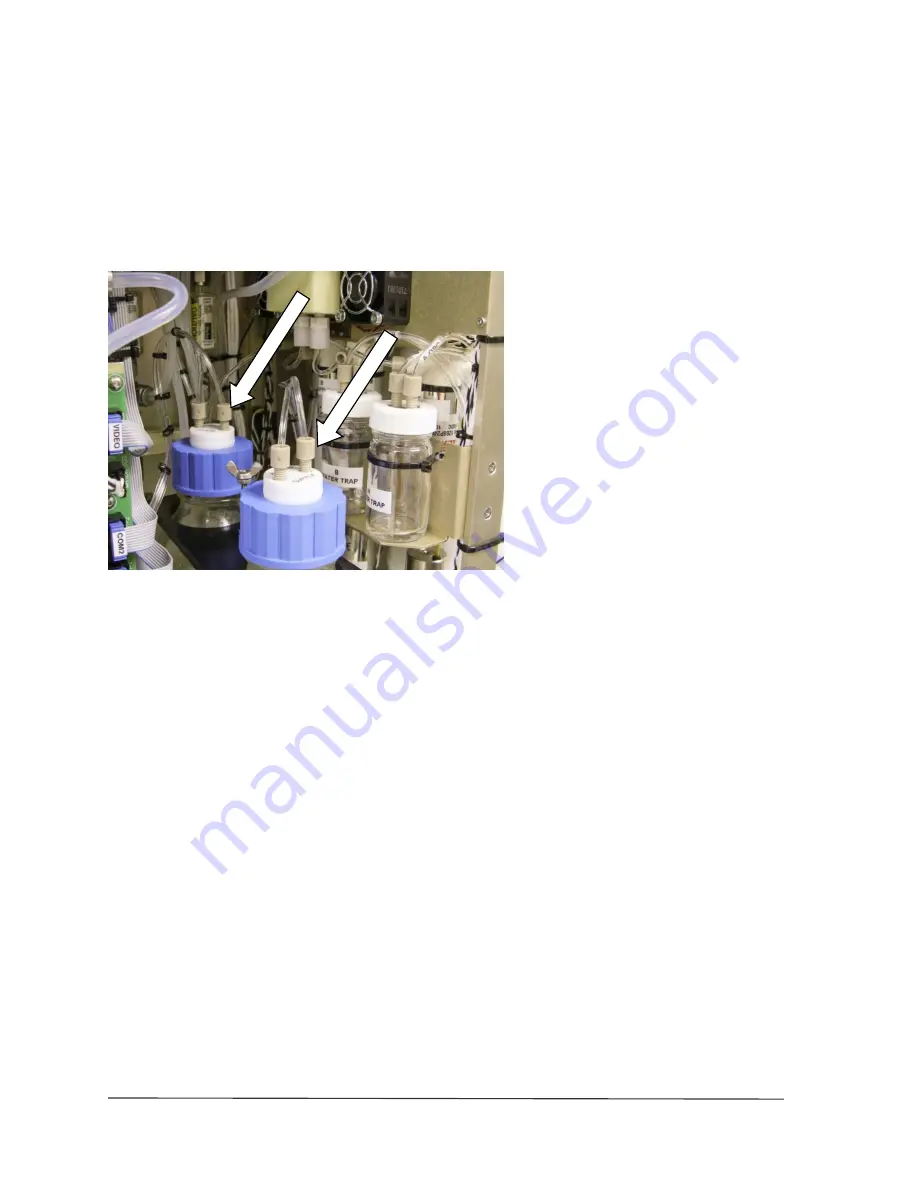
and outlet are at ambient pressure. For aircraft operation, the vents must be reconnected to the 
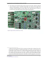
bottle caps (Figure 8).  


Figure 8: Vents Connected to Bottle Caps (for Aircraft Operation) 

2.1


Mounting Considerations 

Refer to Appendix D for mounting hole locations. The CCN-200 must always be mounted in an upright 
configuration. The back panel is the structural component of the CCN-200 and is a 1/8-inch, 6061-T6 
aluminum plate. All of the major internal components mount with stainless steel fasteners to this 
aluminum plate, and critical mounting screws have helicoil inserts for strength.   
For best performance, the environmental temperature of the CCN-200 should be kept as low as 
possible without freezing. For more details, see section 3.3 “operating limits”. 

2.2


Power Supply Considerations 

The CCN-200 is designed to operate on 28 VDC power. Ground-based applications require a line 
voltage to 28 VDC supply, which can be either a linear or switching supply. The capacity of the supply 
should be at least 25 A. The CCN-200 may draw this current load for up to a few minutes at startup, 
and then will typically draw 20 A in normal operation. 
If there are high frequency spikes when the 400 Hz power is converted to 28 VDC, this can cause 
problems with the CCN-200. If problems occur when operating the CCN-200  in an aircraft 
environment, check the line voltage to 28 VDC supply. A 28 VDC aircraft cable with a filter is included 
and should be used for aircraft operation. 

Summary of Contents for CCN-200

Page 1: ...Dual Column Cloud Condensation Nuclei Counter Operator Manual for Dual Column CCN DOC 0128 Revision F 2400 Trade Centre Avenue Longmont CO 80503 USA...

Page 2: ...demarks or registered trademarks of their respective owners Warranty The seller warrants that the equipment supplied will be free from defects in material and workmanship for a period of one year from...

Page 3: ...OLUMN CCN counter Water entering the inlet will wet the temperature sensor causing erratic readings and throw the entire temperature control system off In addition liquid water will plug the sheath ai...

Page 4: ...Instrument Components 24 4 4 Air and Water Flows 28 4 4 1 Sample and Sheath Air Flows 30 4 4 2 How the System Maintains Pressure and Removes Excess Water 30 5 0 Power and Communication Connections 32...

Page 5: ...DMT Tab Accesses Service Tabs 78 12 7 Program Input Files 84 12 8 Program Output Data 85 12 8 1 Serial Stream 85 12 8 2 Output Files 87 13 0 SS Settings Config Editor 89 14 0 CCN Calibration Editor ex...

Page 6: ...8 Figure 17 Air and Water Flow for Column B 29 Figure 18 Location of Power Communications Sample and Exhaust Connections 32 Figure 19 Power Supply and Controller Boards with Important LEDs Identified...

Page 7: ...t Tab 75 Figure 49 Histograms 76 Figure 50 Flow A Chart 76 Figure 51 Serial Output Tab in Normal Mode 77 Figure 52 DMT Service Tab 78 Figure 53 Text Box for Entering Password to Access DMT Service Tab...

Page 8: ...is functioning properly The following sections describe these steps in detail Any time the CCN is shipped it must be dried out and properly repacked prior to shipment Failing to follow proper procedu...

Page 9: ...ed on the bench top AC DC power supply which is also in the kit The white wire labeled 28V connects to 28V VDC and the black wire labeled RETURN connects to the return of the power supply If a longer...

Page 10: ...d the location of the four mounting holes c Remove the four hole plugs from the front of CCN case d Connect the cables to the screen e Mount the screen to the case using the four 4 7 mm screws with lo...

Page 11: ...ocated inside the CCN 200 frame Figure 3 This memory stick should be kept in this location as it contains important information about the instrument White papers describing the theory behind the CCN d...

Page 12: ...am starts click the Dry Start Up button shown in Figure 4 Note by default the Dry Start Up and Dry Shut Down buttons disappear after 20 seconds but the user can configure this time setting using the S...

Page 13: ...n 1 1 In general the switch should be set to the 16 second position because when the pump operates every 2 seconds water may infiltrate the CCN without generating an alarm However the 2 second positio...

Page 14: ...ATA Shut off power to the CCN instrument and send the data file to DMT at CCN INFO dropletmeasurement com 1 5 Verify the CCN 200 has been set up correctly Before performing the tests below ensure the...

Page 15: ...mes The average measured flow should be 10 of the stated flow on the Flows tab 5 Remove the filter from the inlet of the CCN and set the following supersaturation gradient scans Supersaturation Settin...

Page 16: ...When the unit has pumped down below approximately 400 mb go into the Flows tab and turn off the Air Pump This will turn off power to the pump which will also act as a seal 5 If unit does not pump dow...

Page 17: ...inlet to the CCN counter Liquid water will plug the sheath air filter and shut off flow If liquid water does enter the inlet IMMEDIATELY SHUT OFF THE INSTRUMENT If a small amount of water less than a...

Page 18: ...ers to this aluminum plate and critical mounting screws have helicoil inserts for strength For best performance the environmental temperature of the CCN 200 should be kept as low as possible without f...

Page 19: ...CCN 200 Figure 9 is based on the design of Dr Greg Roberts of Scripps Institute of Oceanography Dr Athanasios Nenes of Georgia Institute of Technology did the CCN 200 s theoretical parameterization Th...

Page 20: ...f automatically scanned supersaturation settings 250 Optical Particle Counter Laser 660 nm 35 mW Flow Range Total flow 200 1000 volume cc min factory calibrated at 500 Vccm Sample flow 20 100 Vccm She...

Page 21: ...l and data logging Touch screen control and display Serial data output for external computer Calibration Comparison of CCN Counter output to reference instruments Differential Mobility Analyzer DMA an...

Page 22: ...principle that diffusion of heat in air is slower than diffusion of water vapor Roberts and Nenes 2005 Inside the columns a thermodynamically unstable supersaturated water vapor condition is created a...

Page 23: ...s on the temperature difference between the top and bottom of the column the flow rate and the absolute pressure in the column A unique feature of the instrument is that each column has three temperat...

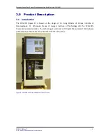
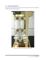
Page 24: ...TECHNOLOGIES 2 4 4 3 Instrument Components The picture on the inside of the manual s front cover shows the front view of the CCN 200 with important components labeled Figure 11 Figure 11 Side View of...

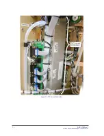
Page 25: ...tion Nuclei Counter CCN 200 DOC 0128 Rev F 2 5 2017 DROPLET MEASUREMENT TECHNOLOGIES Figure 12 Figure 13 Figure 14 and Figure 15 show close ups of some of the components that are not easily visible in...

Page 26: ...DOC 0128 Rev F 2017 DROPLET MEASUREMENT TECHNOLOGIES 2 6 Figure 13 TEC Current Controllers...

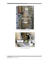
Page 27: ...Manual Dual Column Cloud Condensation Nuclei Counter CCN 200 DOC 0128 Rev F 2 7 2017 DROPLET MEASUREMENT TECHNOLOGIES Figure 14 Sheath Flow Filters and Frits Figure 15 Proportional Valves Proportiona...

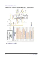
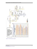
Page 28: ...0128 Rev F 2017 DROPLET MEASUREMENT TECHNOLOGIES 2 8 4 4 Air and Water Flows Diagrams of the air and water flows for the two CNN 200 columns Figure 16 Figure 17 Figure 16 Air and Water Flow for Colum...

Page 29: ...Operator Manual Dual Column Cloud Condensation Nuclei Counter CCN 200 DOC 0128 Rev F 2 9 2017 DROPLET MEASUREMENT TECHNOLOGIES Figure 17 Air and Water Flow for Column B...

Page 30: ...nge is needed to reach the dew point at the top of the column The air in the column passes through the Optical Particle Counter OPC 22 It enters a chiller 29 which drops the dew point of the air so th...

Page 31: ...ump is controlled independently of the computer However this pump in the CCN counter operates only when the TEC relay power is turned on The toggle switch for this pump which is labeled SW1 is located...

Page 32: ...plit into two 28 VDC legs of which all four pins must be used Pins A and C 28 VDC Pins B and D Power Return 12 awg wire must be used between the power source and the power connector The white wire is...

Page 33: ...cation Keyboard The standard keyboard connection This can be used with the touch screen or with a standard monitor Mouse The mouse connection which is active with the touch screen or a standard monito...

Page 34: ...l What It Means when LED is Illuminated A 12 V power supply on Power Supply Board is present B 5 V power supply for computer is present C Watchdog pulse is present blinks at 1 Hz in tandem with watchd...

Page 35: ...nter CCN 200 DOC 0128 Rev F 3 5 2017 DROPLET MEASUREMENT TECHNOLOGIES NOTE D1 D2 and D3 are lit all the time when there is power supplied to the instrument These boards are installed behind other boar...

Page 36: ...re the 28 to 12V power supply boards for the current controllers The LED on these boards indicates whether power is being supplied to the controller Figure 21 depicts the board for Column A with the L...

Page 37: ...nsumption rate is as follows 9 6 ml per hour when Liquid Flow Set on Flows tab is low 14 4 ml per hour when Liquid Flow Set is medium 36 0 ml per hour when Liquid Flow Set is high 5 Make sure the caps...

Page 38: ...as described in section 8 4 3 Replace both the Nafion humidifier membranes 4 alibrate the Absolute Pressure Transducer as described in section 8 3 7 5 Pump Diaphragm and Motor Maintenance Requirement...

Page 39: ...tion Equipment Aerosol Generator System for nebulizing ammonium sulfate particles DMT Aerosol Generator AG 100 Differential Mobility Analyzer TSI3080L or equivalent CN Particle Counter TSI3025L or equ...

Page 40: ...the SS calibration curve for the CCN instrument Figure 25 The curve is very linear down to 0 1 Running SS below 0 1 will require special calibration and interpretation Below 0 1 SS growth kinetics be...

Page 41: ...nt flow meter the range should be from 10 1000 Vccm USB stick that accompanies the CCN this contains initial factory calibration data to be used as a reference as well as a spreadsheet to run the regr...

Page 42: ...he Dual CCN exe software click on the DMT Service tab Click just below the text window in the middle of the screen In the white text box that appears type in the password Service Then select the Flow...

Page 43: ...isplayed in the Sample Flow Vccm field in the volts column Because Step 4 sets the regression coefficients to 1 and 0 the Sample Flow Vccm indicator is now actually displaying the voltage from the sam...

Page 44: ...working with 3 In the Dual CCN exe software click on the DMT Service tab Click just below the text window in the middle of the screen In the white text box that appears type in the password Service T...

Page 45: ...ment as the X value 8 2 2 3 Verification Click the Manual Override button off Ensure the flow is set to 500 Vccm and the flow ratio is 10 0 25 Measure the total flow with flow meter and compare to the...

Page 46: ...bin where the calibration particles are measured A good calibration exists if the particles are in the proper bin or slightly high If the particles are in a lower size bin the OPC could be dirty and w...

Page 47: ...ump to the OPC block Figure 30 4 5 Note the beam dump orientation wedge points down towards inside of OPC and make sure its o ring 2 011 OR011 is accounted for 6 Insert the tube on the end of an inert...

Page 48: ...t s protective housing and replace the two 2 56 screws holding the Beam Dump to the OPC block Figure 32 9 Turn power back on and verify 1st Stage Monitor voltage has returned to normal operating value...

Page 49: ...Operator Manual Dual Column Cloud Condensation Nuclei Counter CCN 200 DOC 0128 Rev F 4 9 2017 DROPLET MEASUREMENT TECHNOLOGIES Figure 32 OPC Assembly Exploded View...

Page 50: ...e is too high OPC fogged or flooded Run OPC dry air recirculation on high for 12 hours If this does not clear the problem refer to section 8 4 3 for further instructions Flow Status light is yellow Sh...

Page 51: ...rity of the resistance reading to reverse 1 If at all possible make sure that the CCN instrument has not operated for the previous few hours so that there are no temperature differences between the si...

Page 52: ...oltage is identified on the silkscreen near the LED and if the LED is not lit the problem is most likely in the fuse or power supply Table 1 lists the fuses in the CCN values and applications The fuse...

Page 53: ...g using a syringe or other suction device Note if any water is removed 4 Reinstall the inch Nafion drain plug Unstable flow or flow noise returns after removing water droplets from the sheath line Naf...

Page 54: ...o maximize its length 8 Gently slide one end of Nafion membrane onto Nafion Insertion Tool Figure 33 9 Insert tool into Nafion block and push through other end There is a blind hole at the bottom that...

Page 55: ...than T3 CCN is overcounting or undercounting particles Sheath filter is failing and passing particles Note this is only a possibility if the CCN is over counting Replace sheath filter Refer to Append...

Page 56: ...ue will be up to 5 V If the value drops from 5 V when the OPC heater turns on the fogging is minor and will clear usually in 30 minutes or less If the OPC circulation pump is not at high speed it shou...

Page 57: ...arts Selecting dry shut down will prompt the user to shut the sheath flow metering valves for both columns and install Drierite on the inlet The liquid supply pump will be turned off and the drain pum...

Page 58: ...CN unit into the case noting the orientation the back of the Dual Column CCN frame goes toward the side of the case with the extra foam block 6 Attach the top half of the case noting the orientation o...

Page 59: ...unning or the program will not operate properly Four programs are provided Dual CCN exe operates the CCN unit This is the main program SS Settings Config Editor exe sets up the supersaturation tables...

Page 60: ...the instrument The lower left quadrant displays controls and displays for Column B Particle count graphs for both columns are located in the upper right The bottom right quadrant displays time series...

Page 61: ...rtup the window shows the time available to select a supersaturation table The Date indicator displays current date The Time indicator displays the current computer time Current File displays the name...

Page 62: ...tings are loaded and cannot be altered During the first 20 seconds of program operation the user can also select Dry Start Up or Dry Shut Down This can be done using the radio buttons shown in Figure...

Page 63: ...e SS Table In Figure 38 the CCN is currently operating on supersaturation level in Row 1 which has a corresponding supersaturation of 0 4 Remember that displayed rows start with 0 Note that if the CCN...

Page 64: ...anual Input Selection is Delta T Current SS enables the user quickly to see what SS the currently selected Delta T Set C is equal to Figure 41 The default value for Delta T Set C is the last setting t...

Page 65: ...e at the CCN manifold Note Regardless of the actual air temperature T Sample will be close to ambient temperature as the sample air temperature adjusts to ambient temperature by the time it reaches th...

Page 66: ...eeded before the entire unit is stabilized and data are consistent The light will turn off during SS changes For small SS changes the light will typically be off for less than one minute If the Column...

Page 67: ...CN is operated in a room with substantial air conditioning and the temperature of the air in the room is less than the dew point of the sampled air aerosol changes can occur When the CCN adjusts set t...

Page 68: ...Vccm although the instrument can process flows from 200 1000 Vccm Valve Set V displays the voltage sent to the proportional valve that regulates the total airflow through the CCN Every proportional v...

Page 69: ...T3 Read the air pump switch will be overridden and the air pump will be turned off The user may also want to switch off the air pump during a leak test or when drying the OPC with canned air Air Pump...

Page 70: ...ion to reflect larger particles only Bins lower than the Bin Setting do not have their particles included in the concentration calculation If all particles are to be included Bin Setting should be 0 w...

Page 71: ...ge Mon indicates whether the OPC is fogged The normal operating range for this voltage is less than 0 4 volts If the OPC is fogged this voltage may be as high as 5 volts If this happens turn up the te...

Page 72: ...e An alarm is triggered by a probable problem and will put the CCN in safe mode Safe mode shuts off the TEC relay and Liquid Supply Pump The relevant monitor button will turn red The timers in the sta...

Page 73: ...eshold factory default 10 counts sec Alerts after 20 minutes Alarms after 120 minutes Alert Code 64 Column Temps Stabilized Status counts when T1 T2 or T3 is 0 4 degrees from its set point Alerts afte...

Page 74: ...00 If you select User Defined and specify the number of minutes in the minutes pop up field however files will not start on the hour So if you set Start New File Every x min to User Defined and set mi...

Page 75: ...t Tab The Chart tab Figure 48 is grouped with the tabs for Column B It contains controls for configuring the time series charts in the bottom right quadrant of the Dual CCN window The green slider at...

Page 76: ...ation on configuring the histogram display see section 16 0 12 4 Time Series Charts In the lower right of the Dual CCN window are several time series charts Flows charts for both Column A and Column B...

Page 77: ...nstrument generates a user defined stream of serial output These options are described in more detail below The radio buttons in the upper left of the Serial Output tab Figure 51 allow users to select...

Page 78: ...tiple channels at once Note that the order of channels must follow that in the list of all available channels 12 6 DMT Tab Accesses Service Tabs The DMT tab Figure 52 is used to access the CCN service...

Page 79: ...current session The PID Settings sub tab does not have a Save button as users should not generally modify the PID settings in the configuration To exit the DMT service tab select the Error sub tab an...

Page 80: ...the proportional valve voltage window the PID loop can control Each proportional valve has an operating range of about 1 V but turn on voltages between valves can vary from 1 25 3 5 V Thus one proport...

Page 81: ...e their own Offset Gains sub tabs Figure 55 displays the sub tab for Column A This tab allows users to enter the slope and intercept of the equation to convert SS to Temperature Gradient SS to TG Temp...

Page 82: ...ave the voltageof a column s transducer displayedinthe column s respective CCN 200 Flows tab navigate the Flow Calib sub tab for that column Then enter a slope of 1 and a intercept of 0 This can be us...

Page 83: ...pful when troubleshooting with DMT s help but they should not be modified without assistance Press exit on this tab to exit the DMT Service tab and end service mode Although the unit will function nor...

Page 84: ...iles CCN_SS_Settings ini and CCN_Calibration ini The former stores the supersaturation settings for the instrument while the latter stores instrument calibration and configuration information Both of...

Page 85: ...d is provided with the startup kit The control for this is the Serial Output button found on the Program Control tab section 12 2 6 The data appears on the DB 9 connector labeled Data Out and uses a R...

Page 86: ...the column on the right Current SS A Bin A Column Temp Stabilized A Number Conc A Delta T A Overflow A T1 A Read Bin Array A T2 A Read Bin B T3 A Read Number Conc B T Nafion A Overflow B T Inlet A Bin...

Page 87: ...rnet connection The frequency at which the program starts a new file can be set on the Program tab Use the New File Every min control depicted in Figure 46 If the setting for this parameter is 20 the...

Page 88: ...Number Conc A Sheath Flow B T3 Set A Valve Set A Sample Pressure B T3 Read A Current SS B Laser Current B Nafion Set A Temps Stabilized B Overflow B T Nafion A Delta T B Baseline Mon B Inlet Set A T1...

Page 89: ...pper right changes the display from Column A tables to Column B tables Figure 59 shows the configuration editor program displaying the first table for Column A When configuring supersaturation tables...

Page 90: ...Dry Shut Down options If Start Delay sec is set to 30 for instance the user will have 30 seconds after the Dual CCN exe program starts during which to select a dry start up or shut down Following the...

Page 91: ...rcept calibrate the proper temperature gradient to achieve the desired supersaturation Users who want to calibrate the CCN unit must contact DMT prior to making any adjustment The flow measurements on...

Page 92: ...old and the OPC relative to temperatures at points on the column These differentials are in degrees Celsius Under normal operations these differentials should not be changed but increasing TOPC T3 can...

Page 93: ...ld never be changed The Sealevel Card Installed indicator is illuminated whenever the Sealevel card is present This indicator should be ON if your computer has this card Some older computers have four...

Page 94: ...ration9 A user selectable chart see section 15 2 The Read a File button opens a file explorer for selecting the data file to be read The program then displays this file path in a window at the top of...

Page 95: ...using the Playback Speed slider control shown in Figure 63 Figure 63 Playback Speed Control Users can also change the current time manually using the timing controls on the left side of the screen Fig...

Page 96: ...must disable autoscaling see below before you modify fields in this way Many charts also display options for scaling and copying the data when you right click on them which brings up a drop down menu...

Page 97: ...the CCN 200 User administrator CCN Password password 17 1 To allow remote connections on the CCN computer 1 Open the System by clicking the Start button right clicking Computer and then clicking Prope...

Page 98: ...ur account and follow the instructions on the screen 17 5 To start Remote Desktop on the computer you want to work from 1 Open Remote Desktop Connection by clicking the Start button In the search box...

Page 99: ...ing OK navigate back to the host machine desktop Bring up Windows Explorer and in the path field type followed by the IP address of the remote desktop computer The shared folder should now be visible...

Page 100: ...4 indicates a problem with the total flow or with the sample sheath flow ratio An alarm code of 16 indicates a problem with the sample temperature Problems with both the flow and the sample temperatur...

Page 101: ...en totally dried out such as after shipping Dry Shut Down An option that can be selected during the first ten seconds of the CCN 200 Dry Shut Down should only be selected when the unit needs to be tot...

Page 102: ...ample air The air that the CCN 200 samples for aerosol particles The sample air is confined to a small volume at the center of the CCN 200 column It is surrounded by sheath air with the sheath sample...

Page 103: ...h column T Sample C output channel that indicates the temperature of the sample air When T Sample C exceeds range for a sustained period the CCN 200 computer generates an Alarm Code Note that T Sample...

Page 104: ...operly For a given column the watch dog light on the instrument should blink at the same time as this indicator If the indicator light is steady OFF or ON reboot the computer Zero Count Test A CCN 200...

Page 105: ...particle concentrations however supersaturations below 0 2 show a decreased maximum count rate Note that observed and theoretical maximum concentrations differ considerably On a theoretical level the...

Page 106: ...DOC 0128 Rev F 2017 DROPLET MEASUREMENT TECHNOLOGIES 1 0 6 Appendix C Assy Cable 28V Power...

Page 107: ...Operator Manual Dual Column Cloud Condensation Nuclei Counter CCN 200 DOC 0128 Rev F 1 0 7 2017 DROPLET MEASUREMENT TECHNOLOGIES Appendix D Dual CCN Mounting Hole Locations...

Page 108: ...t accompanies the CCN 200 Figure 3 contains numerous research articles and instrument specific calibration data Appendix F CCN 200 Aircraft Inlet The CCN 200 Aircraft Inlet Schematic is similar to the...

Page 109: ...f you do not have access to a CN counter the following procedure can be used to test the sheath filter A bad sheath filter will still zero count when a good filter is connected to the inlet This is du...

Page 110: ...ntenance kit will support the CCN for one year of continuous operation Major items 4 sheath filters 1 Nafion membrane 1 pump diaphragm repair kit Spare Parts Kit This kit contains items that could fai...

Page 111: ...ction 9 22 11 D Revised entire manual All Omitted schematics Appendices 4 18 12 D 1 Clarified instructions for fixing stuck reeds 10 0 5 13 13 D 2 Corrected baud rate 13 8 1 1 24 14 D 3 Revised OPC Cl...

Reviews: