DOC-0128 Rev F
© 2017 DROPLET MEASUREMENT TECHNOLOGIES
3 4
6.0
Printed Circuit Boards
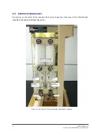
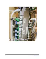
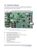
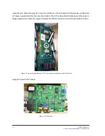
The CCN-200’s controller, power supply, and CDPE boards are located to the left of the Nafion block, as
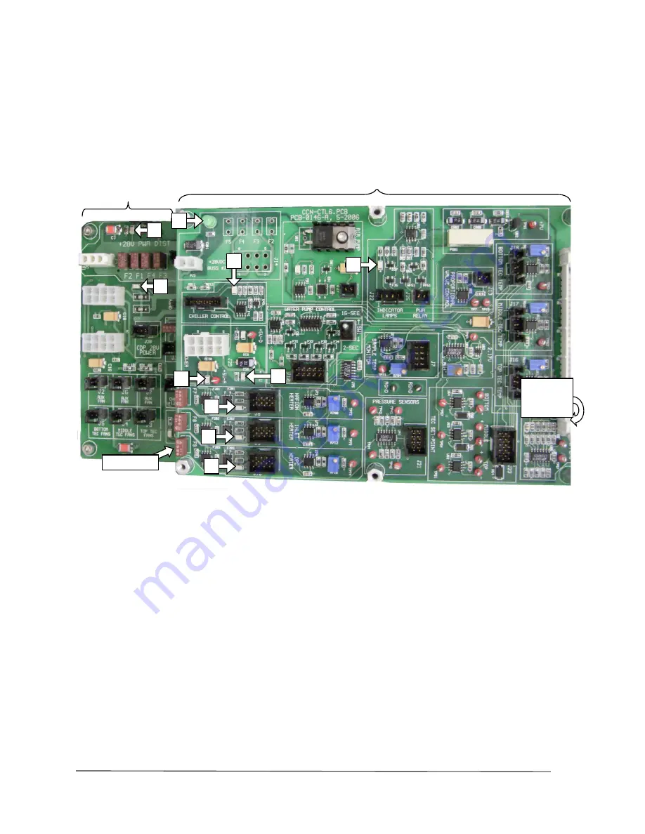
shown in the diagram on the inside cover of this manual. Figure 19 shows a close-up of the controller and
power supply boards, while Figure 20 depicts the CDPE board.
* The Power Supply Board expands underneath the Controller Boards
Figure 19: Power Supply and Controller Boards with Important LEDs Identified
Label What It Means when LED is Illuminated
A
12 V power supply on Power Supply Board is present
B
5 V power supply for computer is present
C
Watchdog pulse is present (blinks at 1 Hz in tandem with watchdog light)
D
Power is supplied to chiller—will cycle around
E
5 V power supply on Controller Board is present
F
12 V power supply on Controller Board is present
G
Power is supplied to Nafion Heater
H
Power is supplied to inlet heater
I
Power is supplied to OPC heater
J
TEC Relay is ON
K
28 V power is present in unit
L
5 V power supply on Power Supply Board is present
A (Hidden
D
H
Controller boards (Column A board is stacked on top of Column B Board
Power Supply Board*
B
(Hidden)
J
E
G
I
C
F
K
L

