Manual, Ultra High Sensitivity Aerosol Spectrometer (UHSAS)
DOC-0210 Rev E-4
4 9
© 2017 DROPLET MEASUREMENT TECHNOLOGIES
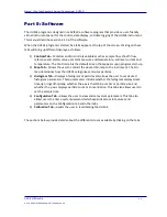
Note:
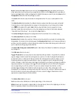
Pressing the
Save
button saves not only the
Configuration
tab parameters but those on
other tabs as well, such as flow rates, sample times, and so on. (The
Map
tab is the exception; it
has its own
Save
button.) After configuring the UHSAS the way you want it, pressing
Save
on the
Configuration
tab will retain the settings you want.
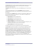
The
Load
button loads a saved instrument configuration file. The user is prompted for a file
name.
The
Data File Path
field specifies the default directory where data files are saved and loaded.
This directory can be changed either by typing in a new directory or by clicking on the folder
icon
to the right of the path.
Note
:
When using the folder icon to navigate to a new
directory, select the desired directory in the file dialog box and then hit the button labeled
“Press ME! Don’t Press Save.” Do not press the
Save
button.
The
Active Config
field displays the configuration file the instrument is currently using.
The
Instrument Port
should be set to COM1.
Broadcast Port
indicates the number of the serial port to which the instrument is sending data,
if applicable. If a serial port is not being used, the
Broadcast Port
field is set to zero and data are
written only to the data file on the computer. Note that the information being sent to the serial
port is identical to that going to the data file.
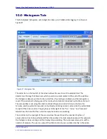
The
Normalize Histograms to Bin Width
switch determines the default normalization setting for
the histogram.
The
Difference
field is not used.
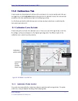
Trigger Threshold
is a very important and somewhat subtle parameter. It specifies the smallest
signal voltage (in Volts on G3) that will register as a particle. It is like the lowest threshold on a
typical instrument, in that events that are smaller than this signal size will not initiate a count.
Everything above this signal size will initiate a count, as long as the event satisfies the timing
criteria. However, in this instrument, the trigger threshold may not have anything to do with the
lowest selected bin. For example, the trigger threshold might be set to 0.100 V with this signal
size corresponding to a 55 nm particle. The user can select a lowest bin of 60 nm, so that
particle triggers between 55 and 60 nm will not appear as counts. (They will appear in the
underflow bin if underflow counting is selected; see section 0.) Or, the user could select a lowest
bin of 50 to 54.9 nm. No counts will appear in this bin, since the trigger threshold is set to a
signal size corresponding to a 55 nm particle.
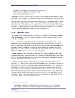
The
Optical Block Pot
is not used.
Vref
should be either 10000 mV or 10240, depending on the instrument.
Offset
allows user to specify a voltage offset in the electronics chain of the highest gain channel
(G3). It is typically a few mV and should not be important.


