WJ-8611 DIGITAL VHF/UHF RECEIVER
5-8 CIRCUIT
DESCRIPTIONS
Digital Signal Processing. The Digital Control PC Assembly (A2)
monitors the level of this signal, and is gain controlled to prevent the signal
level from exceeding 0.2 V peak-to-peak. In addition to these IF outputs,
the 2nd LO/2nd Converter PC Assembly (A3A2) produces the reference
signals that provides the time-base for the Digital Control PC Assembly
(A2) and all of the synthesizers in the RF Tuner Assembly (A3)
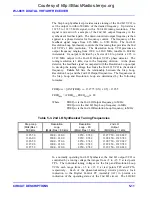
The 1350 MHz IF entering the assembly at connector A3A2E5 is
immediately applied to a double-balanced mixer, where it is mixed with
the 1327.75 to 1330.249 MHz 2nd LO signal. This conversion process
creates the receiver’s 21.4 MHz 2nd IF signal and provides the 1 kHz
tuning resolution. For example, for RF tuned frequencies ranging from
20.851 to 23.350 MHz, the 1st LO/ 1st Converter PC Assembly (A3A1)
produces an IF output spectrum with the signals of interest positioned
within the 1349.150 to 1352.649 MHz range. This 2.5 MHz wide IF
spectrum is applied to the 2nd Converter input. The 2nd converter tunes
within this 2.5 MHz range, in 1 kHz increments, to center the desired
signal in the 21.4 MHz 2nd IF passband. A 20.851 MHz RF input signal
appears as 1351.649 MHz at the 2nd Converter input. If the receiver is
tuned to this RF frequency, the 2nd LO synthesizer produces a 1330.249
MHz LO signal, thus down-converting the desired signal (1351.649 MHz -
1330.249 MHz = 21.4 MHz). A 23.350 MHz RF signal appears as
1349.150 MHz at the 2nd converter input. If the receiver is tuned to this
RF frequency, the 2nd LO synthesizer is tuned to 1327.75 MHz, and this
signal is down-converted to 21.4 MHz (1349.150 MHz - 1327.750 MHz =
21.4 MHz). The IF spectrum is bandpass filtered and then split into two
signal paths. The first signal path provides amplification and filtering to
provide the 21.4 MHz Signal Monitor output at the receiver rear panel, via
A3A2J1. The second path is further processed to produce the 250 kHz IF
output.
From the 2nd converter, the 21.4 MHz signal is directed through an
attenuation circuit that provides from 0 to 31 dB of attenuation. The level
of attenuation is controlled by the Digital Control PC Assembly (A2) , via
the IF 1, 2, 4, 8, and 16 control lines (A2P3, pins 13 through 17). These
lines form a five-bit parallel word. Its binary value determines the amount
of attenuation in 1 dB increments. Test points TP46 and TP47 permit
verification that the 8 dB attenuation stage is selected. When the 8 dB
stage is selected, the even-numbered test point (TP46) is at logic low and
its odd-numbered counterpart is at logic high. This pattern prevails with
the other attenuation control monitoring points. TP48 and TP49 monitor
the 4 dB attenuation stage. TP50 and TP51 monitor the 2 dB attenuation
stage. TP52 and TP53 monitor the 1 dB attenuation stage. TP54 and TP55
monitor the 16 dB attenuation stage. (Refer to
signal is amplified and further filtered down to a 200 kHz bandwidth to
limit the bandwidth of the signal that is sent to the Digital Control PC
Assembly (A2). A third conversion is used to produce the final 250 kHz
IF output at A3A2P1. At the 3rd converter, the 21.4 MHz 2nd IF is mixed
with a fixed 21.65 MHz 3rd LO frequency. The resulting 3rd IF, centered
at 250 kHz, is amplified, filtered and presented at A3A2P1. This output is
Courtesy of http://BlackRadios.terryo.org
Summary of Contents for WJ-8611
Page 3: ...A B blank Courtesy of http BlackRadios terryo org...
Page 4: ...THIS PAGE INTENTIONALLY LEFT BLANK Courtesy of http BlackRadios terryo org...
Page 19: ...1 i SECTION 1 GENERAL DESCRIPTION Courtesy of http BlackRadios terryo org...
Page 20: ...1 ii THIS PAGE INTENTIONALLY LEFT BLANK Courtesy of http BlackRadios terryo org...
Page 29: ...2 i SECTION 2 INSTALLATION Courtesy of http BlackRadios terryo org...
Page 30: ...2 ii THIS PAGE INTENTIONALLY LEFT BLANK Courtesy of http BlackRadios terryo org...
Page 47: ...3 i SECTION 3 LOCAL OPERATION Courtesy of http BlackRadios terryo org...
Page 48: ...3 ii THIS PAGE INTENTIONALLY LEFT BLANK Courtesy of http BlackRadios terryo org...
Page 85: ...4 i SECTION 4 REMOTE CONTROL Courtesy of http BlackRadios terryo org...
Page 86: ...4 ii THIS PAGE INTENTIONALLY LEFT BLANK Courtesy of http BlackRadios terryo org...
Page 119: ...5 i SECTION 5 CIRCUIT DESCRIPTIONS Courtesy of http BlackRadios terryo org...
Page 120: ...5 ii THIS PAGE INTENTIONALLY LEFT BLANK Courtesy of http BlackRadios terryo org...
Page 143: ...6 i SECTION 6 MAINTENANCE Courtesy of http BlackRadios terryo org...
Page 144: ...6 ii THIS PAGE INTENTIONALLY LEFT BLANK Courtesy of http BlackRadios terryo org...
Page 167: ...7 i SECTION 7 REPLACEMENT PARTS LIST Courtesy of http BlackRadios terryo org...
Page 168: ...7 ii THIS PAGE INTENTIONALLY LEFT BLANK Courtesy of http BlackRadios terryo org...
Page 243: ...A i APPENDIX A 8611 SM SIGNAL MONITOR OPTION Courtesy of http BlackRadios terryo org...
Page 244: ...A ii THIS PAGE INTENTIONALLY LEFT BLANK Courtesy of http BlackRadios terryo org...
Page 267: ...FP i FOLDOUTS Courtesy of http BlackRadios terryo org...
Page 268: ...FP ii THIS PAGE INTENTIONALLY LEFT BLANK Courtesy of http BlackRadios terryo org...
Page 298: ...Courtesy of http BlackRadios terryo org...


