WJ-8611 DIGITAL VHF/UHF RECEIVER
MAINTENANCE 6-9
3.
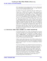
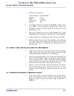
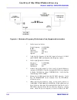
Set the signal generator as follows:
Frequency
250.0000
MHz
Output
Level
See
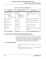
Table 6-2
Modulation
AM, 400 Hz, 50%
4.
Set the receiver IF bandwidth and corresponding signal generator
output level and AM modulation to each of the settings listed in
Table 6-2
. For each of the selected IF bandwidths perform the AM
sensitivity tests describe in
steps 5-7
.
5.
Adjust the receiver attenuation level to produce a reading of at least
0.25 Vrms on the AC voltmeter, with the oscilloscope displaying an
undistorted sinewave. Note the AC voltmeter indication on the dB
scale as a reference level.
6.
While observing the AC voltmeter turn off the signal generator’s
modulation. Note the decrease in the LINE A audio output level
with the modulation removed. The decrease in signal level should
be a minimum of 10 dB less than the level observed in
step 5
,
reflecting a S+N/N ratio of at least 10 dB.
7.
Repeat
steps 5 and 6
using each of the IF bandwidths and
associated signal generator output levels listed in
Table 6-2
.
8.
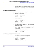
Set the receiver as follows:
Tuned Frequency 250.00000 MHz
Detection
Mode
FM
IF
BW
See
Table 6-2
Gain Control
AGC Fast
Squelch
Off
9.
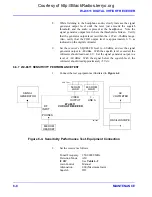
Remove the AC voltmeter from the Line A Audio output, and
connect it to the VIDEO Output, using a 50-ohm termination.
10. Set the receiver IF bandwidth and corresponding signal generator
output level and FM modulation to each of the settings listed in
Table 6-2
. For each of the selected IF bandwidths, perform the FM
sensitivity tests describe in
steps 11-13
.
11. With the signal generator FM modulation on, observe the video
signal level on the AC voltmeter dB scale. Note the AC voltmeter
indication as a reference level.
12. While observing the AC voltmeter, turn off the signal generator’s
modulation. Note the decrease in the video output level with the
modulation removed. The decrease in signal level should be a
minimum of 17 dB less than the level observed in
step 11
, reflecting
a S+N/N ratio of at least 17 dB.
Courtesy of http://BlackRadios.terryo.org
Summary of Contents for WJ-8611
Page 3: ...A B blank Courtesy of http BlackRadios terryo org...
Page 4: ...THIS PAGE INTENTIONALLY LEFT BLANK Courtesy of http BlackRadios terryo org...
Page 19: ...1 i SECTION 1 GENERAL DESCRIPTION Courtesy of http BlackRadios terryo org...
Page 20: ...1 ii THIS PAGE INTENTIONALLY LEFT BLANK Courtesy of http BlackRadios terryo org...
Page 29: ...2 i SECTION 2 INSTALLATION Courtesy of http BlackRadios terryo org...
Page 30: ...2 ii THIS PAGE INTENTIONALLY LEFT BLANK Courtesy of http BlackRadios terryo org...
Page 47: ...3 i SECTION 3 LOCAL OPERATION Courtesy of http BlackRadios terryo org...
Page 48: ...3 ii THIS PAGE INTENTIONALLY LEFT BLANK Courtesy of http BlackRadios terryo org...
Page 85: ...4 i SECTION 4 REMOTE CONTROL Courtesy of http BlackRadios terryo org...
Page 86: ...4 ii THIS PAGE INTENTIONALLY LEFT BLANK Courtesy of http BlackRadios terryo org...
Page 119: ...5 i SECTION 5 CIRCUIT DESCRIPTIONS Courtesy of http BlackRadios terryo org...
Page 120: ...5 ii THIS PAGE INTENTIONALLY LEFT BLANK Courtesy of http BlackRadios terryo org...
Page 143: ...6 i SECTION 6 MAINTENANCE Courtesy of http BlackRadios terryo org...
Page 144: ...6 ii THIS PAGE INTENTIONALLY LEFT BLANK Courtesy of http BlackRadios terryo org...
Page 167: ...7 i SECTION 7 REPLACEMENT PARTS LIST Courtesy of http BlackRadios terryo org...
Page 168: ...7 ii THIS PAGE INTENTIONALLY LEFT BLANK Courtesy of http BlackRadios terryo org...
Page 243: ...A i APPENDIX A 8611 SM SIGNAL MONITOR OPTION Courtesy of http BlackRadios terryo org...
Page 244: ...A ii THIS PAGE INTENTIONALLY LEFT BLANK Courtesy of http BlackRadios terryo org...
Page 267: ...FP i FOLDOUTS Courtesy of http BlackRadios terryo org...
Page 268: ...FP ii THIS PAGE INTENTIONALLY LEFT BLANK Courtesy of http BlackRadios terryo org...
Page 298: ...Courtesy of http BlackRadios terryo org...

