WJ-8611 DIGITAL VHF/UHF RECEIVER
MAINTENANCE 6-13
6.7.1 TYPE 766032 SWITCHING POWER SUPPLY (PS1) PERFORMANCE TEST
1.
Apply power to the receiver and observe the power-up test
sequence.
2.
From the under side of the receiver, locate connector E1 on the Type
797168 Digital Assembly (A2). Refer to
3.
Using the digital voltmeter, measure the output voltages provided by
the power supply at the A2E1 connector. When measuring the
output voltages do not remove connector P1 from the A2E1 as the
power supply load is required for proper voltage regulation. Verify
the voltage levels at the following A2E1 pin connections:
Test
Point Expected
Result
A2E1, pin 1
+13.5 Vdc ±.5V
A2E1, pin 2
+5.5 Vdc +.1V, -0V
A2E1, pin 3
+5.5 Vdc +.1V, -0V
A2E1, pin 6
-13.5 Vdc ±.5V
4.
If the results obtained in step 3 are not as described, check the line
voltage present at pin 3 of the PS1J1 connection. Verify that the
voltage at this connector reflects the current AC line voltage at the
power source.
6.7.2 TYPE 797228 RF TUNER ASSEMBLY (A3) PERFORMANCE TEST
. From the top of the receiver,
observe the status LED indicators near the A3A2E3 connector of the
RF assembly while the receiver powers up. Verify that after power
up, all of the LEDs extinguish except for the REF indicator.
2.
Set the signal generator to produce a 10 MHz CW output signal, at a
level of -5 dBm. Connect the signal generator to the EXT REF
connector at the receiver rear panel. Observe that the REF LED,
DS6, extinguishes and the SENSE LED, DS9, lights. Verify that no
other LEDs are illuminated.
3.
Remove the signal generator from the EXT REF connector.
1st LO/1st Converter PC Assembly (A3A1). Verify that this LED is
extinguished.
5.
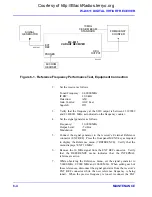
Connect the signal generator to the RF Input of the receiver.
Connect the RF millivoltmeter and 50-ohm load to the SDU Output.
6.
Set the Receiver as follows:
Courtesy of http://BlackRadios.terryo.org
Summary of Contents for WJ-8611
Page 3: ...A B blank Courtesy of http BlackRadios terryo org...
Page 4: ...THIS PAGE INTENTIONALLY LEFT BLANK Courtesy of http BlackRadios terryo org...
Page 19: ...1 i SECTION 1 GENERAL DESCRIPTION Courtesy of http BlackRadios terryo org...
Page 20: ...1 ii THIS PAGE INTENTIONALLY LEFT BLANK Courtesy of http BlackRadios terryo org...
Page 29: ...2 i SECTION 2 INSTALLATION Courtesy of http BlackRadios terryo org...
Page 30: ...2 ii THIS PAGE INTENTIONALLY LEFT BLANK Courtesy of http BlackRadios terryo org...
Page 47: ...3 i SECTION 3 LOCAL OPERATION Courtesy of http BlackRadios terryo org...
Page 48: ...3 ii THIS PAGE INTENTIONALLY LEFT BLANK Courtesy of http BlackRadios terryo org...
Page 85: ...4 i SECTION 4 REMOTE CONTROL Courtesy of http BlackRadios terryo org...
Page 86: ...4 ii THIS PAGE INTENTIONALLY LEFT BLANK Courtesy of http BlackRadios terryo org...
Page 119: ...5 i SECTION 5 CIRCUIT DESCRIPTIONS Courtesy of http BlackRadios terryo org...
Page 120: ...5 ii THIS PAGE INTENTIONALLY LEFT BLANK Courtesy of http BlackRadios terryo org...
Page 143: ...6 i SECTION 6 MAINTENANCE Courtesy of http BlackRadios terryo org...
Page 144: ...6 ii THIS PAGE INTENTIONALLY LEFT BLANK Courtesy of http BlackRadios terryo org...
Page 167: ...7 i SECTION 7 REPLACEMENT PARTS LIST Courtesy of http BlackRadios terryo org...
Page 168: ...7 ii THIS PAGE INTENTIONALLY LEFT BLANK Courtesy of http BlackRadios terryo org...
Page 243: ...A i APPENDIX A 8611 SM SIGNAL MONITOR OPTION Courtesy of http BlackRadios terryo org...
Page 244: ...A ii THIS PAGE INTENTIONALLY LEFT BLANK Courtesy of http BlackRadios terryo org...
Page 267: ...FP i FOLDOUTS Courtesy of http BlackRadios terryo org...
Page 268: ...FP ii THIS PAGE INTENTIONALLY LEFT BLANK Courtesy of http BlackRadios terryo org...
Page 298: ...Courtesy of http BlackRadios terryo org...


