WJ-8611 DIGITAL VHF/UHF RECEIVER
2-6 INSTALLATION
SUPPORT
BRACKET
INSTALLATION
Figure 2-2
illustrates the methods and hardware required to rack-mount
two WJ-8611 receivers in the standard side-by-side configuration. All
illustrated accessory items are furnished with each receiver to facilitate this
installation.
CHASSIS SLIDE INSTALLATION
Jonathan Type 110QD-18-2 chassis slides (not supplied) are designed to
allow installation of a 17-inch wide chassis into a 19-inch wide standard
equipment rack. Capable of supporting loads up to 100 pounds, these
slides mount easily into bracketed equipment racks utilizing machined bar
nuts.
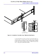
Figure 2-3
illustrates the installation of slide mounts into an
equipment rack, with special attention given to bracket hole spacing.
Each of the Type 110QD-18-2 slide mounts consists of two functional
pieces: a chassis section for mounting to the equipment, and a cabinet
section for mounting to the equipment rack. Three 10-32 x 5/16 pan head
screws are used to install each chassis section to a receiver side panel.
After both chassis sections have been securely tightened to the equipment,
the cabinet sections are installed into the equipment frame. The WJ-8611
Receiver requires 5.25 inches of vertical rack space. Four holes are used
to secure the cabinet section of the slide to the equipment frame mounting
rails. The two inner holes on each bracket secure the slide to the
equipment frame. The two outer holes are used to secure the receiver’s
front panel to the equipment frame. Slide locks permit quick disconnect of
the chassis section of the slide from the cabinet section for equipment
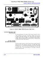
removal. A #10 threaded grounding stud is located on the receiver rear
panel for grounding the receiver to the equipment frame.
2.2.3 POWER REQUIREMENTS
The WJ-8611 Receiver will operate with line voltages ranging from 90 to
264 Vac, at line frequencies from 48 to 440 Hz. Its internal switching
power supply adjusts to accommodate voltages in this range. No external
power source voltage selection is required. The power consumption of the
WJ-8611 Receiver is 50 W, maximum.
Courtesy of http://BlackRadios.terryo.org
Summary of Contents for WJ-8611
Page 3: ...A B blank Courtesy of http BlackRadios terryo org...
Page 4: ...THIS PAGE INTENTIONALLY LEFT BLANK Courtesy of http BlackRadios terryo org...
Page 19: ...1 i SECTION 1 GENERAL DESCRIPTION Courtesy of http BlackRadios terryo org...
Page 20: ...1 ii THIS PAGE INTENTIONALLY LEFT BLANK Courtesy of http BlackRadios terryo org...
Page 29: ...2 i SECTION 2 INSTALLATION Courtesy of http BlackRadios terryo org...
Page 30: ...2 ii THIS PAGE INTENTIONALLY LEFT BLANK Courtesy of http BlackRadios terryo org...
Page 47: ...3 i SECTION 3 LOCAL OPERATION Courtesy of http BlackRadios terryo org...
Page 48: ...3 ii THIS PAGE INTENTIONALLY LEFT BLANK Courtesy of http BlackRadios terryo org...
Page 85: ...4 i SECTION 4 REMOTE CONTROL Courtesy of http BlackRadios terryo org...
Page 86: ...4 ii THIS PAGE INTENTIONALLY LEFT BLANK Courtesy of http BlackRadios terryo org...
Page 119: ...5 i SECTION 5 CIRCUIT DESCRIPTIONS Courtesy of http BlackRadios terryo org...
Page 120: ...5 ii THIS PAGE INTENTIONALLY LEFT BLANK Courtesy of http BlackRadios terryo org...
Page 143: ...6 i SECTION 6 MAINTENANCE Courtesy of http BlackRadios terryo org...
Page 144: ...6 ii THIS PAGE INTENTIONALLY LEFT BLANK Courtesy of http BlackRadios terryo org...
Page 167: ...7 i SECTION 7 REPLACEMENT PARTS LIST Courtesy of http BlackRadios terryo org...
Page 168: ...7 ii THIS PAGE INTENTIONALLY LEFT BLANK Courtesy of http BlackRadios terryo org...
Page 243: ...A i APPENDIX A 8611 SM SIGNAL MONITOR OPTION Courtesy of http BlackRadios terryo org...
Page 244: ...A ii THIS PAGE INTENTIONALLY LEFT BLANK Courtesy of http BlackRadios terryo org...
Page 267: ...FP i FOLDOUTS Courtesy of http BlackRadios terryo org...
Page 268: ...FP ii THIS PAGE INTENTIONALLY LEFT BLANK Courtesy of http BlackRadios terryo org...
Page 298: ...Courtesy of http BlackRadios terryo org...


