WJ-8611 DIGITAL VHF/UHF RECEIVER
INSTALLATION 2-9
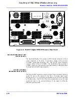
2.2.4 CONNECTOR SIGNALS
With the exception of the front panel PHONES jack, all external input and
output connectors of the WJ-8611 Receiver are located on the rear panel.
Table 2-2
lists all of the external input and output connectors and also
provides a brief description of each connector function. A more detailed
description of the connectors is provided in the paragraphs that follow.
Refer to
Figure 2-4
as a reference for the rear panel connector locations. It
is recommended that only shielded cables be used with the WJ-8611 to
ensure electro-magnetic compatibility with other devices.
RF IN, ANTENNA INPUT (J4)
This N-type connector provides a nominal 50-ohm input for connection of
an antenna or other RF signal source. The receiver is capable of tuning
from 0 to 1000 MHz. The input is capable of withstanding maximum
input signal levels of +20 dBm without damage to the input protection
circuitry.
Table 2-2. WJ-8611 Digital VHF/UHF Receiver
Input/Output Connectors
Connector
Reference
Designator
Description/Function
Mating Connector
(Cage Code)
Comment
RF IN
J4
50-ohm N-Type. RF antenna input or
other signal source.
3031-7388-10
(16179)
Not Supplied
SDU
A3A2J1
50-ohm BNC. 21.4 MHz Signal Monitor
Output.
221165-2
(00779)
Not Supplied
EXT REF
A3A2J2
50-ohm BNC. External Reference Input
(1, 2, 5, or 10 Mhz).
221165-2
(00779)
Not Supplied
COR
A2J6
50-ohm BNC. Carrier-operated-relay
output.
221165-2
(00779)
Not Supplied
VIDEO
A2J8
50-ohm BNC. DC to 1/2 of the selected
IF Bandwidth.
221165-2
(00779)
Not Supplied
250 kHz IF
A2J21
50-ohm SMA. Analog 250 kHz IF
output.
9001-9023-005
(19505)
Not Supplied
LINE
AUDIO
A2TB1
600-ohm Terminal Bus. Line A (1,2,3)
and Line B (4,5,6) audio output.
ELFP06210
(14632)
P/O Accessory
Kit
DIGITAL
IF OUT
J3
15-pin D-Type. Digital IF I/Q data.
3357-9215
(53387)
Not Supplied
RS-232
J1
25-pin D-Type. RS-232 remote serial
interface port.
748050-1
(00779)
Not Supplied
IEEE-488
J2
24-pin Champ. IEEE-488 remote
parallel interface port.
554947-2
(00779)
Not Supplied
POWER
FL1J1
3-prong male receptacle. Line voltage
input (90-264 Vac).
17600
(14632)
P/O Accessory
Kit
Courtesy of http://BlackRadios.terryo.org
Summary of Contents for WJ-8611
Page 3: ...A B blank Courtesy of http BlackRadios terryo org...
Page 4: ...THIS PAGE INTENTIONALLY LEFT BLANK Courtesy of http BlackRadios terryo org...
Page 19: ...1 i SECTION 1 GENERAL DESCRIPTION Courtesy of http BlackRadios terryo org...
Page 20: ...1 ii THIS PAGE INTENTIONALLY LEFT BLANK Courtesy of http BlackRadios terryo org...
Page 29: ...2 i SECTION 2 INSTALLATION Courtesy of http BlackRadios terryo org...
Page 30: ...2 ii THIS PAGE INTENTIONALLY LEFT BLANK Courtesy of http BlackRadios terryo org...
Page 47: ...3 i SECTION 3 LOCAL OPERATION Courtesy of http BlackRadios terryo org...
Page 48: ...3 ii THIS PAGE INTENTIONALLY LEFT BLANK Courtesy of http BlackRadios terryo org...
Page 85: ...4 i SECTION 4 REMOTE CONTROL Courtesy of http BlackRadios terryo org...
Page 86: ...4 ii THIS PAGE INTENTIONALLY LEFT BLANK Courtesy of http BlackRadios terryo org...
Page 119: ...5 i SECTION 5 CIRCUIT DESCRIPTIONS Courtesy of http BlackRadios terryo org...
Page 120: ...5 ii THIS PAGE INTENTIONALLY LEFT BLANK Courtesy of http BlackRadios terryo org...
Page 143: ...6 i SECTION 6 MAINTENANCE Courtesy of http BlackRadios terryo org...
Page 144: ...6 ii THIS PAGE INTENTIONALLY LEFT BLANK Courtesy of http BlackRadios terryo org...
Page 167: ...7 i SECTION 7 REPLACEMENT PARTS LIST Courtesy of http BlackRadios terryo org...
Page 168: ...7 ii THIS PAGE INTENTIONALLY LEFT BLANK Courtesy of http BlackRadios terryo org...
Page 243: ...A i APPENDIX A 8611 SM SIGNAL MONITOR OPTION Courtesy of http BlackRadios terryo org...
Page 244: ...A ii THIS PAGE INTENTIONALLY LEFT BLANK Courtesy of http BlackRadios terryo org...
Page 267: ...FP i FOLDOUTS Courtesy of http BlackRadios terryo org...
Page 268: ...FP ii THIS PAGE INTENTIONALLY LEFT BLANK Courtesy of http BlackRadios terryo org...
Page 298: ...Courtesy of http BlackRadios terryo org...

