WJ-8611 DIGITAL VHF/UHF RECEIVER
6-16 MAINTENANCE
6.
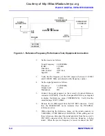
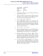
Connect the signal generator to the rear panel RF Input connector.
7.
Set the receiver as follows:
Tuned Frequency 20.00000 MHz
Detection
Mode
USB
Gain Control
AGC Slow
Squelch
Off
8.
Connect the oscilloscope at the Line A audio output.
9.
Set the signal generator to produce a 20.0010 MHz CW output at a
level of -50 dBm.
10. Observe the 1 kHz signal present on the oscilloscope display. Note
the peak-to-peak signal level as a reference.
11. While observing the signal level, slowly tune the signal generator up
in frequency to 20.0030 MHz. Verify that the signal level remains
constant throughout the frequency range.
12. Set the signal generator to 19.9990 MHz, and set the receiver
detection mode to LSB. Note the peak-to-peak signal level on the
oscilloscope as a reference.
13. While observing the signal level, slowly tune the signal generator
down in frequency to 19.9970 MHz. Verify that the signal level
remains constant throughout the frequency range.
14. Remove the oscilloscope from the Line A audio output and connect
it to the Line B output. Repeat steps 9 through 14 for the Line B
output.
15. Remove the test equipment, and reinstall all connectors to the
assembly.
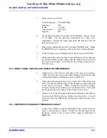
6.7.4 TYPE 797229 FRONT PANEL ASSEMBLY (A1) PERFORMANCE TEST
1.
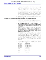
Initiate a COLD START! power-up by holding the front panel “CE”
key pressed while the receiver is powered on. When the message
“COLD START!” is displayed, release the “CE” key.
2.
During the receiver power-up, observe the front panel displays to
determine if the alphanumeric displays and LEDs respond to power-
up display test. If no display activity is observed, check the serial
communications cable (W5), between the Front Panel Assembly
(A1J7) and the Digital Assembly (A2J29), for proper connection.
Verify that connector A1P1 is seated properly on the Digital
Assembly (J5).
Courtesy of http://BlackRadios.terryo.org
Summary of Contents for WJ-8611
Page 3: ...A B blank Courtesy of http BlackRadios terryo org...
Page 4: ...THIS PAGE INTENTIONALLY LEFT BLANK Courtesy of http BlackRadios terryo org...
Page 19: ...1 i SECTION 1 GENERAL DESCRIPTION Courtesy of http BlackRadios terryo org...
Page 20: ...1 ii THIS PAGE INTENTIONALLY LEFT BLANK Courtesy of http BlackRadios terryo org...
Page 29: ...2 i SECTION 2 INSTALLATION Courtesy of http BlackRadios terryo org...
Page 30: ...2 ii THIS PAGE INTENTIONALLY LEFT BLANK Courtesy of http BlackRadios terryo org...
Page 47: ...3 i SECTION 3 LOCAL OPERATION Courtesy of http BlackRadios terryo org...
Page 48: ...3 ii THIS PAGE INTENTIONALLY LEFT BLANK Courtesy of http BlackRadios terryo org...
Page 85: ...4 i SECTION 4 REMOTE CONTROL Courtesy of http BlackRadios terryo org...
Page 86: ...4 ii THIS PAGE INTENTIONALLY LEFT BLANK Courtesy of http BlackRadios terryo org...
Page 119: ...5 i SECTION 5 CIRCUIT DESCRIPTIONS Courtesy of http BlackRadios terryo org...
Page 120: ...5 ii THIS PAGE INTENTIONALLY LEFT BLANK Courtesy of http BlackRadios terryo org...
Page 143: ...6 i SECTION 6 MAINTENANCE Courtesy of http BlackRadios terryo org...
Page 144: ...6 ii THIS PAGE INTENTIONALLY LEFT BLANK Courtesy of http BlackRadios terryo org...
Page 167: ...7 i SECTION 7 REPLACEMENT PARTS LIST Courtesy of http BlackRadios terryo org...
Page 168: ...7 ii THIS PAGE INTENTIONALLY LEFT BLANK Courtesy of http BlackRadios terryo org...
Page 243: ...A i APPENDIX A 8611 SM SIGNAL MONITOR OPTION Courtesy of http BlackRadios terryo org...
Page 244: ...A ii THIS PAGE INTENTIONALLY LEFT BLANK Courtesy of http BlackRadios terryo org...
Page 267: ...FP i FOLDOUTS Courtesy of http BlackRadios terryo org...
Page 268: ...FP ii THIS PAGE INTENTIONALLY LEFT BLANK Courtesy of http BlackRadios terryo org...
Page 298: ...Courtesy of http BlackRadios terryo org...

