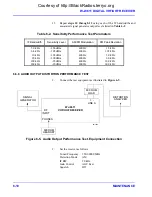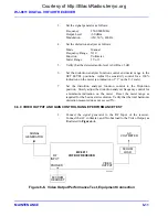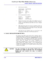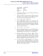
WJ-8611 DIGITAL VHF/UHF RECEIVER
MAINTENANCE 6-17
3.
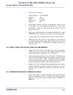
Verify that the configuration switches on the Digital Assembly are
configured for normal front panel operation. Verify that switch 4 of
A2S1 is in the UP position.
4.
Using a digital voltmeter, verify that the proper operating voltages
are being provided at pins 11 and 12 of A1E1. If this voltage is not
present, proceed to the Type 797168 Digital Assembly Performance
test procedure to verify its operation.
5.
Using the oscilloscope, verify the serial communications link with
the Digital Assembly (A2). On the Digital Assembly, connect the
oscilloscope at pin 3 (TXD) of connector J29. Do not remove
connector P2 from J29 when measuring; the pins can be accessed
from the top of the connector. A continuous stream of RS-232 data
should be present at all times, as the receiver communicates display
data to the front panel. If the data from the Digital Assembly is not
present, proceed to the Type 797168 Digital Assembly Performance
test procedure to verify its operation.
6.
Connect the oscilloscope at pin 2 (RXD) of J29. A constant level of
approximately -7 Vdc should be present until one of the front panel
controls is operated. Operate each of the front panel controls and
observe that the data level switches between -7V and +7V as the
control is exercised, and the data is sent from the Front Panel to the
Digital Assembly.
7.
Remove the test equipment and reinstall any connectors removed
during the testing.
6.8 MODULE REMOVAL AND REPLACEMENT PROCEDURES
The procedures that follow provide details associated with the removal and
replacement of the assemblies contained in the WJ-8611 Digital VHF/UHF
Receiver. Refer to the component location drawings provided in
Section 7
of this manual as a reference for the location of these assemblies.
!
CAUTION
This equipment contains components that are subject to
damage from Electrostatic Discharge. Be sure to take
preventative measures when handling the assemblies in
this receiver.
WARNING
Disconnect the Main Supply before removing
the top cover of the WJ-8611. There are
voltages present that could cause electrical
shock.
Courtesy of http://BlackRadios.terryo.org
Summary of Contents for WJ-8611
Page 3: ...A B blank Courtesy of http BlackRadios terryo org...
Page 4: ...THIS PAGE INTENTIONALLY LEFT BLANK Courtesy of http BlackRadios terryo org...
Page 19: ...1 i SECTION 1 GENERAL DESCRIPTION Courtesy of http BlackRadios terryo org...
Page 20: ...1 ii THIS PAGE INTENTIONALLY LEFT BLANK Courtesy of http BlackRadios terryo org...
Page 29: ...2 i SECTION 2 INSTALLATION Courtesy of http BlackRadios terryo org...
Page 30: ...2 ii THIS PAGE INTENTIONALLY LEFT BLANK Courtesy of http BlackRadios terryo org...
Page 47: ...3 i SECTION 3 LOCAL OPERATION Courtesy of http BlackRadios terryo org...
Page 48: ...3 ii THIS PAGE INTENTIONALLY LEFT BLANK Courtesy of http BlackRadios terryo org...
Page 85: ...4 i SECTION 4 REMOTE CONTROL Courtesy of http BlackRadios terryo org...
Page 86: ...4 ii THIS PAGE INTENTIONALLY LEFT BLANK Courtesy of http BlackRadios terryo org...
Page 119: ...5 i SECTION 5 CIRCUIT DESCRIPTIONS Courtesy of http BlackRadios terryo org...
Page 120: ...5 ii THIS PAGE INTENTIONALLY LEFT BLANK Courtesy of http BlackRadios terryo org...
Page 143: ...6 i SECTION 6 MAINTENANCE Courtesy of http BlackRadios terryo org...
Page 144: ...6 ii THIS PAGE INTENTIONALLY LEFT BLANK Courtesy of http BlackRadios terryo org...
Page 167: ...7 i SECTION 7 REPLACEMENT PARTS LIST Courtesy of http BlackRadios terryo org...
Page 168: ...7 ii THIS PAGE INTENTIONALLY LEFT BLANK Courtesy of http BlackRadios terryo org...
Page 243: ...A i APPENDIX A 8611 SM SIGNAL MONITOR OPTION Courtesy of http BlackRadios terryo org...
Page 244: ...A ii THIS PAGE INTENTIONALLY LEFT BLANK Courtesy of http BlackRadios terryo org...
Page 267: ...FP i FOLDOUTS Courtesy of http BlackRadios terryo org...
Page 268: ...FP ii THIS PAGE INTENTIONALLY LEFT BLANK Courtesy of http BlackRadios terryo org...
Page 298: ...Courtesy of http BlackRadios terryo org...

