WJ-8611 DIGITAL VHF/UHF RECEIVER
2-12 INSTALLATION
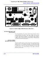
DIGITAL IF OUT (J3)
The Digital IF Output connector (J3) is a 15-pin subminiature-D type
connector that provides a serial interface for post-filtered baseband data in
quadrature-I/Q format. The physical signals are provided as differential-
TTL (RS-422/485), intended to drive 120-ohm terminated twisted pair
wire. The signals may be run single-ended (unterminated) for short
distances. For single-ended operation, it does not matter whether the
differential positive or negative sense is used.
Table 2-3
lists the signals
resident at each pin of this connector.
Table 2-3. Pin Assignments for the DIGITAL IF OUT Connector (J3)
Signal Pin
Description
Clock A
1
10 MHz Shift Clock (differential positive)
Clock B
9
10 MHz Shift Clock (differential negative)
Data A
3
Serial Data (differential positive)
Data B
11
Serial Data (differential negative)
Stb A
2
Start-of-Data Strobe (differential positive)
Stb B
10
Start-of-Data Strobe (differential negative)
I/Q* A
4
I or Q Data Indicator (1 = I, 0 = Q)
I/Q* B
12
I or Q Data Indicator (0 = I, 1 = Q)
5V 14
5V
power
+12V 7
+12V
power
-12V 15
-12V
power
GND 8
Ground
(power)
The data words are 16-bit, twos-complement integers. The words are
paired as complex data points, first I then Q. The complex I/Q pairs are
scaled so that full scale represents a signal 90 dB above the WJ-8611’s
noise floor. The total useful range is approximately 90 dB, as measured
from the noise floor to full scale. The absolute power level represented by
full scale varies with the selected bandwidth. This guarantees that signals
near the noise floor will be represented at any bandwidth. For signals
exceeding the full scale setting, the data will be invalid. Specifically, the
I/Q words’ numeric representation will “wrap” from positive full scale to
negative full scale.
The data rate of the complex I/Q pairs follows the data rates used by the
receiver for demodulation. These rates are:
IF BW
I/Q Pair Data Rate
200 Hz – 1 kHz
3.90625 ksps
3.2 kHz – 6.4 kHz
31.25000 ksps
8 kHz – 20 kHz
62.50000 ksps
30 kHz – 200 kHz
250.00000 ksps
ISB demod (6.4 kHz)
15.625000 ksps
Courtesy of http://BlackRadios.terryo.org
Summary of Contents for WJ-8611
Page 3: ...A B blank Courtesy of http BlackRadios terryo org...
Page 4: ...THIS PAGE INTENTIONALLY LEFT BLANK Courtesy of http BlackRadios terryo org...
Page 19: ...1 i SECTION 1 GENERAL DESCRIPTION Courtesy of http BlackRadios terryo org...
Page 20: ...1 ii THIS PAGE INTENTIONALLY LEFT BLANK Courtesy of http BlackRadios terryo org...
Page 29: ...2 i SECTION 2 INSTALLATION Courtesy of http BlackRadios terryo org...
Page 30: ...2 ii THIS PAGE INTENTIONALLY LEFT BLANK Courtesy of http BlackRadios terryo org...
Page 47: ...3 i SECTION 3 LOCAL OPERATION Courtesy of http BlackRadios terryo org...
Page 48: ...3 ii THIS PAGE INTENTIONALLY LEFT BLANK Courtesy of http BlackRadios terryo org...
Page 85: ...4 i SECTION 4 REMOTE CONTROL Courtesy of http BlackRadios terryo org...
Page 86: ...4 ii THIS PAGE INTENTIONALLY LEFT BLANK Courtesy of http BlackRadios terryo org...
Page 119: ...5 i SECTION 5 CIRCUIT DESCRIPTIONS Courtesy of http BlackRadios terryo org...
Page 120: ...5 ii THIS PAGE INTENTIONALLY LEFT BLANK Courtesy of http BlackRadios terryo org...
Page 143: ...6 i SECTION 6 MAINTENANCE Courtesy of http BlackRadios terryo org...
Page 144: ...6 ii THIS PAGE INTENTIONALLY LEFT BLANK Courtesy of http BlackRadios terryo org...
Page 167: ...7 i SECTION 7 REPLACEMENT PARTS LIST Courtesy of http BlackRadios terryo org...
Page 168: ...7 ii THIS PAGE INTENTIONALLY LEFT BLANK Courtesy of http BlackRadios terryo org...
Page 243: ...A i APPENDIX A 8611 SM SIGNAL MONITOR OPTION Courtesy of http BlackRadios terryo org...
Page 244: ...A ii THIS PAGE INTENTIONALLY LEFT BLANK Courtesy of http BlackRadios terryo org...
Page 267: ...FP i FOLDOUTS Courtesy of http BlackRadios terryo org...
Page 268: ...FP ii THIS PAGE INTENTIONALLY LEFT BLANK Courtesy of http BlackRadios terryo org...
Page 298: ...Courtesy of http BlackRadios terryo org...

