background image

English

Saxo SL 80

Pleaseretainthisdocumentcarefully

Instructionsforinstallation

(GB/IE)

959.010.03.

uK

UK

Summary of Contents for Saxo SL 80

Page 1: ...E n g l i s h Saxo SL 80 Please retain this document carefully Instructions for installation GB IE 959 010 03 uK UK...

Page 2: ...the user will be able to enjoy using his product for many years to come This appliance has a CE marking which means that it complies with the essential requirements of the European gas appliance dire...

Page 3: ...if adjustments are made to the appliance without prior written permission by DRU M J M Gelten General manager DRU verwarming B V Postbus 1021 6920 BA Duiven Ratio 8 6921 RW Duiven www dru nl 3 SAFETY...

Page 4: ...into contact with hot parts 5 Removing the packaging Note the following items when removing the packaging Check the appliance for damages during transport If necessary contact DRU Service After remov...

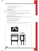
Page 5: ...rs see fig 2 Take the depth of the appliance into account see fig 3 498 mm minimum Determine the location of the appliance Provide a gas connection at the location For details see section 6 3 Make a d...

Page 6: ...instruction for installation 454 1075 399 min 114 max 177 15 15 843 5 40 min 7 5 725 250 27 Tot min 200 cm2 933 5 490 min 108 max 177 40 min 1080 459 725 29 250 7 5 100 100 Tot min 200 cm2 38c 1265 Fi...

Page 7: ...the concentric system supplied by DRU 100 150 mm This system has been tested together with the ap pliance DRU cannot guarantee a proper and safe operation of other systems For connecting to an existi...

Page 8: ...ing through combustible material Attach the wall duct from the outside with four screws in their respective holes 6 5 3 Application with roof duct 6 5 3 1 Construction of concentric system with roof d...

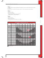
Page 9: ...1 3 bends 2 4 meters horizontal 3 9 meters vertical sloping Construction of this concentric system is not allowed Table 1 Conditions for setting appliance with roof duct G20 G25 Total number of meters...

Page 10: ...entric pipes Caution Make sure that the universal tile fits well with the surrounding tiles Make sure that the adhesive plate fits well onto the flat roof 6 5 4 Connection of existing chimney flue It...

Page 11: ...n elements Check whether the concentric system is placed correctly Check the fixture of the clip binding with parkers on places that cannot be reached later on Maintain sufficient space above the appl...

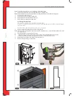
Page 12: ...f components are placed in the control box such as type plate gas control block receiver belonging to the remote control Proceed as follows when placing the control box see fig 6 for details Make an o...

Page 13: ...For that purpose a baffl e is placed and or the air inlet guides are removed The conditions for using a wall duct are described in section 6 5 2 1 and for using a roof duct in section 6 5 3 1 Caution...

Page 14: ...b with its opening towards the pilot flame burner This throttle ring has only 1 hole with a diameter of 7 mm and 1 with a diameter of 13 mm see fig 11 The steps to be taken are described below Take th...

Page 15: ...ray with vermiculite equally spread the vermiculite see fig 15 Caution You can influence the flame image by moving the vermiculite yet the burner deck has to remain covered with vermiculite in order t...

Page 16: ...16 E n g l i s h saxo sl 80 instruction for installation Afb 16a Afb 16b Afb 13 Afb 14 Afb 15 UK...

Page 17: ...17 E n g l i s h saxo sl 80 instruction for installation Afb 16c Afb 16d Afb 16e Afb 16f UK...

Page 18: ...18 E n g l i s h saxo sl 80 instruction for installation Afb 16i Afb 16j Afb 16g Afb 16h UK...

Page 19: ...rd at the bottom Remove the pane 6 10 1 2 Placing the front pane Placing the front pane will take place in reverse order of the removal procedure described above Caution The DRU logo should be at the...

Page 20: ...crew also correspond Connect the black wire with the white plug of thermocouple 2 to the receiver see fig 18 arrow E Caution Make sure that the wires of thermocouple 2 cannot come into contact with ho...

Page 21: ...can vary Check the pre pressure see fig 20 for the measuring nipple on the gas control block Contact the gas company if the pre pressure is not correct 8 3 Ignition pilot burner and main burners For i...

Page 22: ...ective see chapter 11 table 4 under J7 Check if the receiver is defective see chapter 11 table 4 under J8 If necessary correct the above mentioned faults Test the main burner 5x for a good operation 8...

Page 23: ...ck the wood set correctly see section 6 9 Inspect the flue gas discharge combustion air supply system Perform a check as described in chapter 8 10 Delivery You must explain to the user how he should o...

Page 24: ...B No ignition 1 Button A in position MAN 2 Ignition cable runs over and or alongside metal parts 3 Ignition pen corroded 1 Switch button A on the gas control block to ON see fig 19 2 Do not place the...

Page 25: ...eplace batteries Caution Avoid short circuit between the batteries and metal parts of the appliance I Pilot flame is burning but there is no gas flow to the main burner 1 Button A is in position MAN 2...

Page 26: ...4 mm 4x 525070 Spare parkers for mounting the panes 519419 Socket spanner 8 mm 1x 790811 Remote control with receiver 1x 806277 9V block battery 1x 923001 Penlite battery AA type 4x 923100 Squeeze co...

Page 27: ...27 saxo sl 80 Notes...

Page 28: ...DRU Verwarming B V The Netherlands Postbus 1021 NL 6920 BA Duiven Ratio 8 NL 6921 RW Duiven...

Reviews: