24
English
s a x o
s l
80 -
i n s t r u c t i o n
f o r
i n s ta l l at i o n
11. Malfunctions
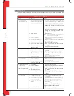
Inthefollowingtableyouwillfindanoverviewofmalfunctionsthatmightoccur,thepossiblecausesandthereme-
dies
Table 3: diagnosis of malfunction
Problem
Possible cause
Remedy
A. Notransmission
(motorwillnotrun)
1. The(new)communicationcode
betweenreceiverandremote
controlmuststillbeconfirmed.
2. Emptybatteries.
3. Receiverisdamaged.
4. Remotecontrolisdamaged.
5. Motorcableatvalveisbroken.
6. Bentpinsofthe8-wireconnector.
7. Ifthereceiverissurroundedby
metal,thiscoulddecreasethe
transmissionrange.
1. Holddowntheresetbuttonofthereceiver,until
youhear2soundsignals;
fig. 21
.Letgoofthere-
setbuttonafterthesecond,longersoundsignal
andpressthebutton
t
ontheremotecontrol
within20sec.,untilyouhearanextralongsound
signalconfirmingthatthenewcodehasbeen
set;see
fig. 21
.
Itispossiblethatyouneedtosetanewcommu-
nicationcode;consulttheUserManual,section
4.2.7,CommunicationCode.
2. Replacebatteries.
!Caution
Avoid short circuit between the batteries
and metal parts of the appliance.
3. Replacethereceiverandconfirm/changethe
code(remedy1)
4. Replacetheremotecontrolandconfirm/change
thecode(remedy1)
5. Replacemotorcableatthevalve.
6. Makesurethatthepinsofthe8-wireconnector
arestraight.
7. Changethepositionoftheantenna.
B. Noignition
1. ButtonAinpositionMAN.
2. Ignitioncablerunsoverand/or
alongsidemetalparts.
3. Ignitionpencorroded.
1. SwitchbuttonAonthegascontrolblocktoON,
see
fig. 19
.
2 Donotplacetheignitioncableoverand/or
alongmetalparts.Thiswillweakenthespark;
see
fig. 19
.
Ifnecessary,replacetheignitioncable.
3. Replacetheignitionpen.
C. Nosoundsignal
1. Receiverisdamaged.
2.60-seconddelaybeforethefull
restartisnotyetfinished.
1. Replacethereceiverandconfirm/changethe
code(remedy1atA)
2.Waituntilthedelaytimehaspassed.
D. Onecontinuoussound
signalof5sec.
(Possible7shortbeepsprior
tothe5sec.soundsignal)
1. Loosewiring.
2. Receiverisdamaged.
3. Bentpinsofthe8-wireconnec-
tor.
4. Damagedmagnetvalve.
5. Thermocouple2stilltoohot.
1. Connectthewiringproperly.
2. Replacethereceiverandconfirm/changethe
code(remedy1atA)
3. Makesurethatthepinsofthe8-wireconnector
arestraight.
4. Replacethegascontrolblock.
5. Waituntilthethermocouplehascooleddown
sufficiently
E. Nopilotflame
1. Airinthepilotflamepipe.
2. Wiresofthermocouple1have
beencross-connected.
3. Nosparkatthepilotflame
burner.
4. Injectorisblockedup.
1. Flushthepipeorstarttheignitionprocess
severaltimes.
2. Checkthepolarityofthethermocouplewiring.
Connectthethermocouplewiringproperly.
3.1 Checkiftheignitioncableislyingfreefrom
metalparts.
Laythemfree,ifnecessary;see
fig. 19
.
3.2 Ifnecessary,replacetheignitioncable.
3.3 Ifnecessary,replacetheignitionpen.
4.1 Cleantheinjector.
4.2 Ifnecessary,replacetheinjector.
UK
Summary of Contents for Saxo SL 80
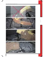
Page 17: ...17 E n g l i s h saxo sl 80 instruction for installation Afb 16c Afb 16d Afb 16e Afb 16f UK...
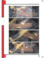
Page 18: ...18 E n g l i s h saxo sl 80 instruction for installation Afb 16i Afb 16j Afb 16g Afb 16h UK...
Page 27: ...27 saxo sl 80 Notes...
Page 28: ...DRU Verwarming B V The Netherlands Postbus 1021 NL 6920 BA Duiven Ratio 8 NL 6921 RW Duiven...


