25
English
s a x o
s l
80 -
i n s t r u c t i o n
f o r
i n s ta l l at i o n
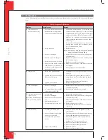
Table 3: diagnosis of malfunction
Problem
Possible cause
Remedy
F. Electronicskeep
sparkingwhilethepilot
flameburns
1. Receiverisdamaged.
1. Replacethereceiverandconfirm/changethe
code(remedy1atA)
G. Pilotflamedoesburn,
butsolenoidvalvecloses
afterca.10secondsor
whentheappliancegets
hot
1. Thermocouple1doesnot
function.
2.Batteries(almost)empty.
1.1 Measurethevoltage,usingadigitalmultimeter,
settomVrange,byconnectingthecablestothe
cableshoe.Thecableshoeislocatedontheout-
side,directlynexttothemagnetnut;see
fig. 22
.
Thevoltageshouldbeatleast5mVwithin20
seconds.
Itmaynotbelowerwhentheapplianceiswarm.
Ifthevoltageistoolow,
-thethermocoupleshouldbeplacedbetterin
theflameor
-thethermocouplemustbereplaced.
1.2 Checkthesizeofthepilotflame.
Correctapilotflamethatistoosmall
1.3 Checkthewiringofthethermocoupletothe
receiver.
Ifnecessary,replacethewiring.
2. Replacebattery.
H. Thereareshortsound
signals,butnosparks
andnosound/clicks
canbeheardofthemag-
netopeningthevalve
1. Batteries(almost)empty.
1. Replacebatteries.
!Caution
Avoid short circuit between the batteries
and metal parts of the appliance.
I. Pilotflameisburning,
butthereisnogasflow
tothemainburner
1. ButtonAisinpositionMAN.
2. Applianceisinthepilotflame
position.
3. Pre-pressureofthegasistoolow.
4. Damagedmagnetvalve.
1. TurnbuttonAonthegascontrolblocktoON;
see
fig. 19
.
2. Increaseflameheightbypressingbutton
s
of
theremotecontrol.
3. Checkpre-pressure.
Ifnecessary,consultthepowercompany.
4. Replacethegascontrolblock.
J. Mainburnersignites,
butgooutagainafter
approx.22seconds.
1. Wiringofthermocouple2is
loose.
2. Wiresofthermocouple2have
beencross-connected.
3. Short-circuitinthewiringof
thermocouple2.
4. Brokenwireinthewiringof
thermocouple2.
5. Thermocouple2isdirty.
6. Thermocouple2isnotposi-
tionedcorrectlyintheflame
(seefig.23.)
7. Thermocouple2isdefective.
8. Receiverisdefective.
1. Connectthewiringproperly.
2. Connectthewiringproperly.
3. Replacewiring.
4. Replacewiring.
5. Cleanthethermocouple.
6. Positionthethermocouplecorrectlyinthe
flame.
7. Checkthevoltageacrossthermocouple2just
beforethemainburnergoesout.
Ifthevoltageislowerthan1.8mV,replace
thermocouple2.
8. Checkthevoltageacrossthermocouple2just
beforethemainburnersgoout.
Ifthevoltageishigherthan1.8mV,replace
thereceiver.
UK
Summary of Contents for Saxo SL 80
Page 17: ...17 E n g l i s h saxo sl 80 instruction for installation Afb 16c Afb 16d Afb 16e Afb 16f UK...
Page 18: ...18 E n g l i s h saxo sl 80 instruction for installation Afb 16i Afb 16j Afb 16g Afb 16h UK...
Page 27: ...27 saxo sl 80 Notes...
Page 28: ...DRU Verwarming B V The Netherlands Postbus 1021 NL 6920 BA Duiven Ratio 8 NL 6921 RW Duiven...


