background image

Foreword

Dear Customer,

We would like to thank you for buying this DRU prod-
uct. Our products have been designed and produced to 
meet the highest possible quality, performance and safety 
requirements, allowing you to enjoy years of problem-free 
use. 

In this booklet you will find instructions for the installation 
and use of your new appliance. Please read these instruc-
tions and the manual carefully to familiarize yourself with 
the appliance. If you require any further support, please do 
not hesitate to contact your supplier. 
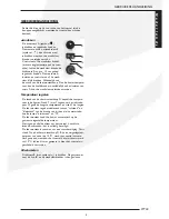
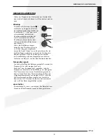
Unpacking

Once the heater has been unpacked, all packaging should 
be disposed of in the regular manner.

Connection

This appliance should be connected by a registered install-
er.

InstructIons for InstallatIon

Type of gas

This appliance can only be used and is only suitable for the 
country and the type of gas mentioned on the type iden-
tification tag. Please check that the local gas and pressure 
correspond with the specifications on the type identifica-
tion tag. All regulations regarding gas installation, including 
any local regulations, must be observed at all times. The 
appliance is to be installed by a competend person.

To operate the heater on propane, it should be converted 
by a competend person. A conversion set can be ordered 
through your supplier.

Important

• Keep curtains and any other flammable materials at least 

50cm away form the appliance.

• Caution! Touching the heater when hot can cause burns 

and blisters!

• The appliance should be installed and maintained by a  

registered installer.

• Do not install any so-called dust filter on or under the 

casing.

• Do not hang wet clothes and towels etc. on the heater to 

dry.

General

The appliance can be mounted either on a wall of incombu-
stible material (e.g. stone or concrete) or on a wall of com-
bustible material (e.g. wood). 

Style 3,4 and 5 on propane (G31) can be placed in vehicles 
pulling mobile units, provided the following is observed:
•  When the appliance is working, the mobile unit must be 

standing still;

•  When the vehicle pulling the mobile unit is being filled 

with fuel, the appliance must be switched off;

•  If glass is broken, switch off the appliance and contact an 

installer;

•  In case of a gas leak, switch off the appliance as well as the 

gas supply tap and contact an installer;

•  Flue gas discharge must remain unobstructed at all times.

Installation to a wall of non-flammable material 

(fig. 6, 8, pg. 58, 59)

The models are suitable for hanging installation only. Allow 
at least 1 metre’s clearance above the heater to enable 
sufficient heat circulation. When installed hanging, at least 
1 m free space should be kept above the appliance to 
allow sufficient heat dissipation. When intalled standing, 
the bottom of the mounting sheet (2) should stand on the 
floor, this is the minimum height between the floor and 
centre of wall duct (size F. fig 6, 8, pg. 58, 59).

The mounting plate (2) serves as a template to mark the 
position of the duct. To be able to hang the casing over 
the interior, a minimal clearance of 25 mm must be allo-
wed between the appliance and a windowsill or suchlike. 
The minimum clear installation height (Y) required for 
each of the various models is listed in the table on page 
60.

The standard wall duct

Drill a horizontal hole in the wall, ø E to take the air-sup-
ply pipe. The wall duct should slope at an angle of approx. 
2º.

The standard wall duct is suitable for walls with a thick-
ness of 50 – 330 mm and the standard extended wall duct 
for walls with a thickness of 50 – 600 mm. Depending on 
the thickness of the wall, the inlet and outlet pipes should 
be made to length, i.e.:


Length of inlet pipe 

Length of outlet pipe

STYLE 3 

Thickness of wall  + 20mm  Thickness of wall + 40mm

STYLE 4, 5 

Thickness of wall + 20mm  Thickness of wall + 30mm

The tension members fixed to the wall grid can be made 
to size after installation

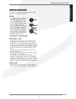
Installation of the standard exterior wall duct 

(fig. 1, 3, page 57)

Slide the adjusted inlet pipe (1) through the mounting 
sheet (2), with the turned-back edge facing the mark (45º 
top left) in the mounting sheet. Slide the sealing ring (3) 
and the wall ring (4) around the inlet pipe, paying attention 
to the order (see figure). Take the whole and slide the 
inlet pipe into the wall opening. Press the mounting 

10

INSTRUCTIONS FOR INSTALLATION

Summary of Contents for Style 3

Page 1: ...nstruzione per l uso IT Manual de instalación y guía del usuario ES Instruçôes de instalaçâo e o instruçâo PT STYLE 3 STYLE 4 STYLE 5 Bewaar dit document zorgvuldig Please retain this document carefully Bewahren Sie dieses Dokument sorgfältig auf Conservez soigneusement cette notice Conservare con cura uesto manuale dell utente Guarde cuidadosamente esta guía para el usuario Conserva esta instruçâ...

Page 2: ...nte que les modèles DRU STYLE sont conformes au certifi cat d examen de type CE E 1490 et qu ils satisfont à la directive européenne relative aux appareils à gaz 2009 142 EC Con la presente dichiariamo che i modelli DRU STYLE sono conformi al Certificato di esame CE di tipo E 1490 e soddisfano i requisiti della direttiva europea 2009 142 EC in materia di apparecchi a gas Por la presente declaramos...

Page 3: ... inlaatpijp 3 Bevestiging van de montageplaat 3 Installatie aan een wand van brandbaar materiaal 3 Installatie van het binnenwerk 3 Aansluiting van de gastoevoer 4 In bedrijf stellen 4 Kleinstand 4 Waakvlambrander 4 Plaatsen van de mantel 4 Belangrijk 4 Gebruikershandleiding 5 Aansteken 5 Temperatuur regelen 5 Uitschakelen 5 Algemene opmerkingen 6 Onderhoud en reiniging 6 Verkleuring van wanden en...

Page 4: ...wordt gevuld met brandstof moet het toestel uit Bij glas breuk schakel het toestel uit en neem contact met een installateur op Bij gaslek schakel het toestel uit en tevens de gas toe voer kraan en neem contact met een installateur op Rookgasafvoer dient ten alle tijden vrij gehouden te wor den Installatie aan een wand van onbrandbaar materiaal fig 6 8 blz 58 59 De modellen kunnen alleen hangend ge...

Page 5: ...ken De montageplaat aandrukken tot tegen de wand Breng de moeren aan op de trekstangen 6 en zet deze tegen de bevestigingsbeugels 5 handvast Bevestiging van de montageplaat fig 1 3 blz 57 Let op stel de montageplaat 2 waterpas zorg ervoor dat de inlaatpijp naar buiten toe afloopt 1cm op 1 m en dat het muurrooster recht tegen de buitenmuur ligt Eventueel condenswater zal dan nooit in het toestel ku...

Page 6: ...nd en bij een geringe warmtebehoefte in twee posities n l kleinstand of uit Hierbij blijft de waakvlam steeds branden De kleinstand kan alleen worden gecon troleerd wanneer de kamertemperatuur hoger is dan ca 15 C 60 F Kleinstand De kleinstand is ingesteld op 20 van het volverbruik De kleinstandschroef is geheel ingedraaid en voorzien van de juiste kleinstandboring Deze is niet instelbaar Waakvlam...

Page 7: ...regelen De stand van de thermostaatknop D bepaalt de tempera tuur in de kamer Stand 7 met 7 tegenover het indicatie punt C geeft de hoogste temperatuur en stand 1 de laagste De thermostaat regelt modulerend tussen volstand en kleinstand van de brander en bij een kleine warmtebe hoefte tussen kleinstand en N De thermostaat houdt de kamer automatisch op de gewenste ingestelde temperatuur Het is geen...

Page 8: ...or Het vertrek waar het toestel zich bevind goed te ventile ren Een goede richtlijn hiervoor is Bij nieuwbouw 3 24 m3 uur per m2 vloeroppervlak van een vertrek Bij bestaande bouw 25 20 m3 uur voor een vertrek Maak zo weinig mogelijk gebruik van kaarsen en olielamp jes en houd het verbrandingslontje zo kort mogelijk Deze sfeerbrengers zorgen voor aanzienlijke hoeveelheden vervuilde en ongezonde roe...

Page 9: ...spuitstuk Draai met een steeksleutel het spuitstuk uit de brander en plaats het nieuwe spuitstuk Sluit tenslotte de onderdelen in omgekeerde volgorde weer aan STYLE 3 3 Kleinstelspuitstuk fig 9 pag 61 Steek het kleine kapje met de naam Junkers erop uit de kap van het gasregelblok Verwijder de kap van het gas regelblok door schroef 1 te verwijderen Verwijder nu het kleinstelspuitstuk 3 aan de boven...

Page 10: ...8 ...

Page 11: ...stening the mounting sheet 11 Installation to a wall of inflammable material 11 Connection of the gas supply 11 Operations 12 The low setting 12 Pilot light burner 12 Placing the housing 12 Important 12 Operating instructions 13 Lighting 13 Temperature controle 13 Switching off 13 General notes 14 Gas safety regulations for installation use 1998 14 Cleaning and Maintenance 14 Discoloration of wall...

Page 12: ...the mobile unit is being filled with fuel the appliance must be switched off If glass is broken switch off the appliance and contact an installer In case of a gas leak switch off the appliance as well as the gas supply tap and contact an installer Flue gas discharge must remain unobstructed at all times Installation to a wall of non flammable material fig 6 8 pg 58 59 The models are suitable for h...

Page 13: ...e fas tening clamps Press the mounting sheet up to the wall Appply the screw nuts onto the tension members 6 and tighten them by hand against the fastening clamps 5 Fastening the mounting sheet fig 1 3 page 57 Caution Level the mounting sheet make sure that the inlet pipe goes down towards the outside 1 cm to 1 m and that the wall grid lies straight against the exterior wall Then any condensation ...

Page 14: ...e low or off In this situa tion the pilot light keeps burning The low setting can only be checked when the room temperature is higher than 15 C 60 F The low setting The low setting has been adjusted to 20 of the full consumption The low setting screw has been fully tight ened and is supplied with the correct low setting bore This is not adjustable Pilot light burner Upon delivery the pilot light b...

Page 15: ...will determine the temperature in the room Setting 7 with 7 opposite the indicator C will give the highest temperature and setting 1 the lowest The thermostat regulates the heater in modulation between HIGH and LOW burner settings and if only a little warmth is required between LOW and N The thermostat automatically keeps the room at the required temperature There is absolutely no objection to the...

Page 16: ... ventilation for example or by cigarette smoke or candles These problems can be avoided by ensuring that the room the heater is in is properly ventilated A good guideline for ventilation is New buildings 3 24 m3 hour per m2 floor surface of the room Existing buildings 25 20 m3 hour for a room Use candles and oil lamps as little as possible keeping the wick as short as possible While they enhance t...

Page 17: ... burner and fit the new jet Reconnect the components in reverse order STYLE 3 3 Fine adjustment jet fig 9 page 61 Poke the top with the name Junkers on it out of the cover of the gas control block Remove the cover of the gas control block by unscrewing the screw 1 Now remove the fine adjustment jet 3 at the top of the gas control block Fit the new fine adjustment jet and tighten firmly Replace the...

Page 18: ...16 ...

Page 19: ... Installation der Giebeldurchführung mit Teleskopeinlassrohr 19 Befestigung der Montageplatte 19 Installation der Innenausrüstung 19 Anschluss der Gaszuleitung 20 Inbetriebnahme 20 Kleinstand 20 Zündflammenbrenner 20 Anbringen des Mantels 20 Wichtig 20 Gebrauchsanweisung 21 Zündung 21 Temperatur regeln 21 Ausschalten 21 Allgemeine Bemerkungen 22 Wartung und Reinigung 22 Verfärbung von Wänden und D...

Page 20: ...rt werden Die Style 3 4 und 5 die mit Propan G31 betrieben werden dürfen in mobile gezogene Wagen eingebaut werden wenn die folgenden Voraussetzungen erfüllt sind Wenn das Gerät in Betrieb ist muss der Wagen stillste hen Wenn das Fahrzeug das den Wagen zieht mit Kraftstoff gefüllt wird muss das Gerät ausgeschaltet sein Bei Glasbruch muss das Gerät ausgeschaltet werden und Sie müssen Kontakt mit ei...

Page 21: ... dass die eingelassenen Befestigungsbügel 5 auf der horizontalen Mittellinie liegen siehe Markierung in der Montageplatte und um die umgesetzte Montageplatte haken Bringen Sie den Dichtungsring 3 und den Mauerring 4 an der Hälfte des Einlassrohrs an siehe Zeichng 2 für die richtige Reihenfolge Nehmen Sie das Ganze und schieben Sie die Einlassrohrhälfte von innen durch die gemachte Maueröffnung in ...

Page 22: ...dienungshahn darf beim Anschließen an die Gaszufuhrleitung nicht verdreht werden Vermeiden Sie Spannungen auf Bedienungshahn und Leitungen Kontrollieren Sie die Anschlüsse auf Gasdichtheit Inbetriebnahme Das Gerät ist von der Fabrik für die Gasssorte die auf der Typenplatte steht eingerichtet Der Thermostat regelt modulierend zwischen Vollstand und Kleinstand und bei geringem Wärmebedarf in zwei P...

Page 23: ...terbrennt Je nach der Stellung des Bedienungsknopfs D und den Stellung der eventuel len Fernbedienung wird den Hauptbrenner nach dem Loslassen von Knopf A von der Zündflamme entzündet Temperatur regeln Je nach der Stelllung des Bedienungsknopfs D werden die Flammen höher oder weniger hoch sein Steht die 7 dem Anzeigepunkt C gegenüber sind die Flammen am höchsten und bei Stellung 1 am niedrigsten D...

Page 24: ...wenn der Raum in dem sich das Gerät befindet gut ventiliert wird Eine gute Richtlinie hierfür ist Bei Neubau 3 24 m3 Stunden pro m2 Bodenoberfläche eines Raums Bei bestehendem Bau 25 20 m3 Stunden für einen Raum Gebrauchen Sie möglichst wenig Kerzen und Öllampen und halten Sie den Verbrennungsdocht so kurz wie möglich Diese Stimmungsmacher sorgen für ziemliche Mengen schmutziger und ungesunder Ruß...

Page 25: ...em Steckschlüssel die Düse aus dem Brenner und bringen Sie die neue Düse an Schliessen Sie danach die Zubehörteile in umgekehrter Reihenfolge wieder an STYLE 3 3 Kleinstelldüse Zeichng 9 Seite 61 Drücken Sie die kleine Kappe mit dem Namen Junkers aus der Kappe des Gasregelblocks Entfernen Sie die Kappe des Gasregelblocks indem Sie die Schraube 1 entfernen Entfernen Sie nun die Kleinstelldüse 3 an ...

Page 26: ...24 ...

Page 27: ... de travesée de façade avec conduite d amanée téléscopique 27 Fixation de la plaque de montage 27 Installation contre un mur en matériau inflammable 27 Installation de l ouvrage interne 28 Connextion de l alimentation en gaz 28 Mise en marche 28 Débit réduit 28 Brûleur de la veilleuse 28 Installation du manteau 28 Important 28 Mode d emploi 29 Allumage 29 Réglage de la température 29 Extinction 29...

Page 28: ...être aussi bien fixé à un mur fait en maté riau ininflammable comme la pierre ou le béton qu à un mur en matériau inflammable comme le bois Les Style 3 4 et 5 au propane G31 peuvent être installés dans des habitations mobiles pour autant qu ils remplissent les conditions suivantes Lorsque l appareil est en marche l habitation mobile doit rester à l arrêt Lorsque le véhicule de traction de l habita...

Page 29: ... du côté de l appareil doit être d une longueur égale à l épaisseur du mur 20 mm ATTENTION Ne pas couper les composants de la conduite du côté où les colliers de fixation ont été placés Installation du conduit de traversée de façade avec conduite d amenée téléscopique fig 1 3 p 57 Par l extérieur introduisez la grille du mur avec la moitié de la conduite d amenée montée dessus dans l ouverture du ...

Page 30: ...our le raccordement un robinet à raccord agréé pour la Belgique celui ci doit avoir l agrément B G V Le robinet doit être fixé en dehors du manteau Autres spécificités Faites le vide d air du conduit d alimentation avant de brancher définitivement l appareil Il est interdit de tourner le robinet de commande lors du branchement à l alimentation en gaz Évitez toute tension sur les conduits et sur le...

Page 31: ...re maximale si vous choisissez la position 1 vous obtenez la température minimale Le thermostat fait varier le débit du brûleur entre la valeur minimale et la valeur maximale pour atteindre et maintenir la température requise Pour l obtention de tempéra tures peu élevées le thermostat fait diminuer le débit du brûleur jusqu la valeur minimale ou coupe l alimentation en gaz du brûleur Le thermostat...

Page 32: ...uvelles constructions 3 24 m3 heure par m2 de surface au sol dans la pièce Pour les constructions existantes 25 20 m3 heure pour la pièce Il est recommandé d utiliser le moins souvent possible des bougies et des lampes à huile et si c est le cas la mèche devrait être la plus courte possible Ces éléments d ambiance sont à l origine de quantités considérables de particules de suie salissantes et mal...

Page 33: ...e clé plate déposez l injecteur montés sur le brûleur désaccouplez l injecteur et montez le nouvel injecteur Ensuite remontez les pièces et composants dans l ordre inverse de leur dépose STYLE 3 3 Injecteur à débuit réduit fig 9 pag 61 Dégagez le petit écusson Junkers de la coiffe du bloc de régulation de l alimentation de gaz Déposez la coiffe du bloc de régulation de l alimentation de gaz en dév...

Page 34: ...32 ...

Page 35: ...erno con tubo telescopico d immissione 35 Fissaggio della piastra di montaggio 35 Installazione della parte interna della stufa 35 Allacciamento alla rete del gas 36 Messa in funzione 36 Consumo ridotto 36 Bruciatore della fiamma pilota 36 Posizionamento dell involucro 36 Importante 36 Iistruzioni per l uso 37 Accensione 37 Regolazione della temperatura 37 Spegnimento 37 Indicazioni generali 38 Ma...

Page 36: ...le ad es in mattoni o in cemen to sia a una parete in materiale infiammabile ad es in legno Gli Style 3 4 e 5 a propano G31 sono installabili in carrelli da traino sempre che soddisfino i seguenti requisiti Quando l apparecchio è in funzione il carrello da traino deve rimanere fermo Quando il carrello da traino viene riempito di combusti bile l apparecchio deve essere spento In caso di rottura del...

Page 37: ... i pezzi del tubo al lato in cui sono montate le staffe di fissaggio Installazione del condotto attraverso il muro esterno con tubo telescopico d immissione fig 1 3 p 57 Dall esterno inserire la griglia a muro con metà del tubo d immissione montato nell apertura fatta nel muro pres tando attenzione a sistemarla secondo l indicazione Top Inserire l altra metà del tubo d immissione attraverso la pia...

Page 38: ... con accoppiamento per il Belgio deve avere il mar chio B G V Il rubinetto con accoppiamento dovrà essere inserito all infuori dell involucro Inoltre vale Sfiatare la tubatura d alimentazione prima che l apparecchio venga collegato Non torcere il rubinetto di comando facendo l allacciamento alla tubatura d alimentazione del gas Evitare tensioni sul rubinetto rubinetto di comando e le tubature Cont...

Page 39: ...io la posizione minima é n 1 Il punto indicatore C per la manopola del termostato é situato a sinistra di detta manopola Il termostato regola modulando tra l uso massimo e l uso minimo e desiderandolo una temperatura ambiente piau bassa tra l uso minimo e spento e mantiene automaticamente l ambiente alla temperatura desiderata Il radiatore avendo la camera di combustione stagna rispetto all ambien...

Page 40: ...tte o di candele Il problema può essere prevenuto arieggiando bene la stanza dove si trova l apparecchio Una buona direttiva a tale proposito è la seguente in edifici di nuova costruzione 3 24 m3 ora per m2 di superficie di una stanza in edifici già esistenti 25 20 m3 ora per una stanza Limitare l uso di candele e di lumi ad olio e tenere lo stop pino più corto possibile Queste luci creano un atmo...

Page 41: ...una chiave a forchetta doppia svitare il giunto e l iniettore dal bruciatore rimuovere l iniettore dal giunto e montare il nuovo iniettore Collegare infine i pezzi seguendo l ordine inverso STYLE 3 3 Iniettore per il consumo ridotto fig 9 pag 61 Estrarre il cappuccio su cui è riportato il nome Junkers dal coperchio del blocco dei comandi Rimuovere il coperchio dal blocco comandi del gas togliendo ...

Page 42: ...40 ...

Page 43: ...talación en pared de material combustible 43 Instalación del interior del aparato 43 Conexión a la conducción de gas 44 Puesta en servicio 44 Posición de mínimo 44 Quemador de llama contínua 44 Colocación de la cubierta 44 Importante 44 Manual de uso DRU ART 45 Encendido 45 Regulación de temperatura 45 Apagado 45 Recomendaciones generales 46 Mantenimiento y limpieza 46 Cambios en el color de pared...

Page 44: ... se pueden colocar en vehículos que remolquen vehículos móviles siempre que cumplan lo siguiente Cuando el aparato esté en funcionamiento el vehículo deberá estar parado Cuando el vehículo que remolca el vehículo móvil se llene de combustible el aparato tendrá que estar apagado En caso de que se rompa el cristal apague el aparato y póngase en contacto con el instalador En caso de que haya una fuga...

Page 45: ... preste atención de que los estribos de sujeción solda dos 5 esten en el centro ver las marcas en la plancha de montaje y se sujeten en el borde ligeramente doblado de la plancha de montaje A continuación coloque la arandela de cierre 3 y la aran dela de pared 4 en la mitad del tubo ver figura para un orden correcto Tome todo el conjunto e introduzca la mitad del tubo interior en la apertura de la...

Page 46: ...s cañerías Compruebe si las conexiones de gas están bien ajustadas Puesta en servicio El aparato ha sido adaptado desde fábrica al tipo de gas indicado en la placa que especifica el tipo El termostato regula de manera modular entre máximo y mínimo y en caso de una necesidad pequeña de calor en dos posiciones a saber mínimo o apagado en ambos casos la llama continua permanece encendida La posición ...

Page 47: ... mina la temperatura de la habitación La posición 7 indica el máximo y la posición 1 el mínimo El termostato regula modularmente entre máximo y mínimo del quemador y en caso necesario entre mínimo y El aparato puede permanecer en posición de encen apagado El termostato mantiene la habitación a la tem peratura deseada No hay contraindicación alguna en dejar el aparato encen dido por las noches el s...

Page 48: ...osas por la quema de polvo por una mala ventilación por el humo del tabaco o por quema de velas Estos problemas puede ser evitados ventilando la habit ación donde se encuentra el aparato de manera adecuada A título de información Para construcciones nuevas 3 24 m3 hora por cada m2 de suelo de habitación Para construcciones existentes 25 20m3 hora por habit ación Use velas y lámparas de aceite lo m...

Page 49: ...eva Ajuste a continuación los componentes en orden inverso a como los ha aflojade STYLE 3 3 Inyector regulador pequeño figura 9 pag 61 Retire la tapita con el nombre Junkers de la tapa del bloque regulador del gas Quite la tapa del bloque regulador del gas desenroscando el tornillo 1 Retire a continuación el inyector regulador pequeño 3 que se encuentra en la parte superior del bloque regulador de...

Page 50: ...48 ...

Page 51: ...m tubo de entrada telescópica 51 Montagem de armaçâo 51 Instalaçâo contra um muro de material combustível 51 Instalaçâo do interior 51 Ligação do abastecimento de gás 52 Pôr em marcha 52 Nivel pequeno 52 Bico pilôto 52 Colocar a armaçâo 52 Importante 52 Instruçoes de uso 53 Acender 53 Ajustar a temperatura 53 Desconectar 53 Observaçoes gerais 54 Manutenção e limpeza 54 Queimar para a primeira vez ...

Page 52: ...aterial à prova de fogo p ex pedra ou betão quanto em uma parede de material inflamável p ex madeira Os Style 3 4 e 5 a propano G31 podem ser colocados em carros móveis contanto que se considere o seguinte Quando o aparelho estiver em funcionamento o carro tem de estar parado Ao atestar o carro com combustível é necessário desligar o aparelho Em caso de quebra de vidros desligue o aparelho e con t...

Page 53: ...ha com a metade do tubo de entrada mon tada neste desde a fora na abertura de muro feito com Topo para cima colocando a grelha Empurre outra metade do tubo de entrada pela armação e verifique que os tiradores inseridos 5 se encontrem na linha horizontal vê os sinais da armaçâo e enganchem por tràs o bordo de forro dobrado Pôr o anel de estanque 3 e o anel de muro 4 em volta da metade do tubo Vê o ...

Page 54: ...ira de admissão não pode ser retorcida quando é ligada ao tubo de entrada de gás Evite as tensões na torneira de admissão e nos tubos Verifique a vedação hermética das ligações Pôr em marcha O aparelho é construido na fàbrica pelo género de gás como indicado na chapa de modelo O termostato regula a maneira modulando entre nível grande e nível peg ueno com pouca necessidade e calor entre dois nivel...

Page 55: ...o do termostato D determina a tem peratura no espaço A posiçâo com 7 em frente O ponto de indição C procura a temperatura mais alta e a posiçâo 1 a temperatura mais baixo O termostato regula em maneira modulanda entre o nível grande e peguena do bico e com a neccesidade pequena entre pequena e des ligado O termostato tem o espaço automaticamente no tem peratura ajustada desejada Não há uma objecçã...

Page 56: ...nte por fumar cigarros ou por acender velas Estes problemas podem ser evitados por uma boa venti lação do quarto onde se encontra o aparelho Uma boa directiva para isto Em novas construções 3 24 m3 hora de superfície de chão de um quarto Em construções existentes 25 20 m3 hora para um quarto Não utiliza muitas velas ou candeias e mantenha o rastilho mais curto que possível Estes criadores de ambie...

Page 57: ...ustamento de precisão fig 9 pág 61 Retire a pequena cobertura com o nome de Junkers da caixa do bloco de controlo de gás Remova a caixa do bloco de controlo de gás tirando o parafuso 1 Em seguida remova a cabeça de injector de ajustamento de precisão 3 do lado de cima do bloco de controlo de gás Coloque a nova cabeça de injector de ajustamento de precisão apertando a bem Coloque a caixa de novo ST...

Page 58: ... Kleinstand consommation débit réduit consumo ridotto m3 h 0 071 0 035 0 123 0 028 0 132 0 038 Branderspuitstuk burner injector Brennerdüse injecteur brûleur iniettore bruciatore Mm Ø 1 50 0 85 1 65 1 10 2 00 1 15 Waakvlamspuitstuk pilot light injector Zündflammendüse injecteur veilleuse iniettore fiamma pilota kode 51 30 51 30 51 30 Kleinstelspuitstuk low setting injector Kleinstelldüse injecteur...

Page 59: ...57 fig 1 STYLE 3 fig 2 STYLE 3 fig 3 STYLE 4 5 fig 4 STYLE 4 5 STYLE ...

Page 60: ...58 fig 6 STYLE 3 fig 5 STYLE 3 ...

Page 61: ...59 STYLE fig 7 STYLE 4 5 fig 8 STYLE 4 5 ...

Page 62: ...gorie II2L3P I2EK3P II2L3P I2EK3P II2L3P I2EK3P Gassoort G25 G25 3 G31 G25 G25 3 G31 G25 G25 3 G31 Branderdruk mbar 14 6 29 14 8 30 12 5 30 Nom Belasting Hs kW 3 00 2 70 4 00 4 80 5 20 5 45 Nom Belasting Hi kW 2 70 2 43 3 60 4 32 4 70 4 91 Nom Vermogen kW 2 20 2 00 2 90 3 50 3 80 3 98 Verbruik volstand l h 366 100 430 179 562 203 Verbruik kleinstand l h 98 30 132 59 162 53 Branderspuitstuk mm Ø 1 ...

Page 63: ...61 STYLE fig 10 2 1 3 4 5 6 7 7 6 5 4 3 2 1 3 711 7 2 4 5 6 1 3 38c 927 fig 9 ...

Page 64: ......

Reviews: