background image

English

T R I O

 - 

I N S T R U C T I O N


F O R


I N S TA L L AT I O N

8.4 Flame picture

The flame picture can only really be assessed when the appliance has been burning for several hours. Volatile com-
ponents from paint, materials, etc., which evaporate in the first hours, will affect the flame picture.


Check whether the flame picture is acceptable.


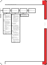
Consult the malfunction search diagram (Chapter 11) if the flame picture is not acceptable.

9.  Maintenance

Once a year the appliance should be checked, cleaned and, if necessary, repaired by a competent installer in the field 
of atmospheric gas heating.
Check at least whether the appliance is working properly and safely.

Caution


-  

Close the gas tap when performing maintenance work;

-  

Check the gastightness after repair;

-  

After replacing the thermocouple you should first tighten the swivel of the gas control block by hand and then give 
it another quarter turn with a suitable spanner.

-  

SS-absolutely do not clean the concentric system (internally) with a steel brush or metal sponge, for example. This 
will damage the oxide skin and could lead to leaks in the system as a result of pitting corrosion.


If required, clean the following components:
-  

the pilot flame burner;

-  

the combustion room;

-  

the panes.

!Caution

  Only clean a glass pane once it has reached room temperature.

!Caution 

  -  Avoid damage to the glass pane(s).

-  Avoid/remove fingerprints on the glass pane(s), as they will burn into the glass.
-  Clean the glass pane(s) as described in the user manual.
-  Regularly remove accumulated dirt, as it can burn into the glass.
-  

Do not use the appliance when a glass pane is broken and/or cracked, until it has been replaced as described from 
section 6.9

Caution


-  

If necessary, place back the wood set correctly; see section 6.8.


Inspect the flue gas discharge / combustion air supply system;

!Caution

  You must always perform a final inspection.


Perform a check as described in chapter 8.

Parts requiring replacement can be obtained from your supplier.

10  Delivery

You must explain to the user how he should operate the appliance. You should instruct her/him for instance on using 
the appliance for the first time, the operation of the remote control, annual maintenance.

Caution


-  

Tell the user to close the gas tap immediately in case of malfunctions/bad performance and contact the installer in 
order to prevent dangerous situations;

-  

Indicate the location of the gas tap;

-  

Point out the precautions in the user manual against unintended ignition by other wireless remote controls such as 
car keys and garage door openers.


Instruct the user about the appliance and the remote control.


When the appliance is started for the first time, point out that
-  

when the appliance is stoked up for the first time, volatile components evaporate from paint, materials, etc.;

-  

when evaporating the appliance should preferably be set at the highest level;

-  

the room should be well ventilated.


Give the user manual and installation manual to the user (the installation manual should be kept near the appliance).

14

Summary of Contents for Trio RCE G20

Page 1: ...E n g l i s h Trio RCE G20 G25 G25 3 natural gas Please retain this document carefully Instructions for installation 959 064 04 EN EN...

Page 2: ...uct for many years to come This appliance has a CE marking which means that it complies with the essential requirements of the European gas appliance directive As an installer you must be competent in...

Page 3: ...druservice com Product gas fired heating appliance Type Trio RCE Conformity assessment agency Kiwa 0063 Applicable EC regulation 2016 426 EU Applied harmonized standards NEN EN 613 NEN EN 613 A1 R P...

Page 4: ...uld have after removing the packaging Remove both woodscrews from the bottom plate connecting the appliance to the platform Caution The glass pane s is are made of a ceramic material Very small irregu...

Page 5: ...RU cannot guarantee a proper and safe operation of other systems and cannot accept liability for these systems For connecting to an existing chimney flue you should only use the installation set suppl...

Page 6: ...inner plate if necessary on a heat resistant intermediate plate when passing through combustible material Attach the wall duct from the outside with four screws in their respective holes 6 5 3 Applica...

Page 7: ...l pipe length total number of meters vertical and or sloping pipe length 1 2 3 4 5 6 7 8 9 10 11 12 no bends 0 B C D D D E E E E E E E 2 bends 0 A A B C D D D E E E E E 1 A A B C D D D E E E 2 A A B C...

Page 8: ...rs vertical and or sloping pipe length 1 2 3 4 5 6 7 8 9 10 11 12 no bends 0 B C C C C E E E E E E E 2 bends 0 A A B C C C C E E E E E 1 A A B C C C C E E E 2 A A B C C C C E 3 A A B C C C 4 A A B C 5...

Page 9: ...ned Connect the roof duct to the concentric pipes Caution Make sure that the universal tile fits well with the surrounding tiles Make sure that the adhesive plate fits well onto the flat roof 6 5 4 Co...

Page 10: ...ithvermiculiteinordertopreventthatthelifeexpectancyoftheburnerisreduced Fill the tray around the burner with chips equally spread the chips Caution Do NOT place chips over the slot around the burner I...

Page 11: ...e pro cedure described in chapter 8 3 Below we will describe how the receiver is connected 7 1 Receiver The receiver should be connected to the appliance before the batteries are installed Follow the...

Page 12: ...ics connection cable for GV60 Consult DRU s service website The following contacts are possible Ignition connect both contacts 1 3 for one second if there is a 2nd thermocouple the appliance should bu...

Page 13: ...ttempts After igniting the pilot flame the main burner will ignite during the ignition procedure Check whether the main burner continues to burn If the main burner does not continue to burn repeat the...

Page 14: ...urn into the glass Clean the glass pane s as described in the user manual Regularly remove accumulated dirt as it can burn into the glass Do not use the appliance when a glass pane is broken and or cr...

Page 15: ...place rechargeables by alkaline batteries Communication code between remote and receiver has to be re set Press reset button on receiver until brief beep followed by long beep Release reset button and...

Page 16: ...does not fall away Clean with compressed air Rectify Retry 2 05 Check Ignition cable Present and connected Being free from metal parts or concrete Too long cut away all excessive length at receiver e...

Page 17: ...ner dirty Weak pilot flame being drawn away by flames main burner Clean with compressed air See 2 04 2 15 Check Flames too low Supply pressure does not drop away as main burner or other appliances in...

Page 18: ...ith the appliance Table 5 Parts included with the delivery Part Quantity Wood set 1x Installation manual 1x User manual 1x Setting template for baffle 1x Baffle 1x Air inlet guide 1x Spare parkers for...

Page 19: ...ar Main burner injector 1x 1 20 1x 1 40 1x 1 20 1x 1 40 mm Low setting injector 1 6 1 6 mm Efficiency class EN613 1 0 1 0 Useful efficiency NCV Useful efficiency at nominal heat output th nom 87 4 85...

Page 20: ...E n g l i s h TRIO INSTRUCTION FOR INSTALLATION Appendix 3 Parts Parts can be ordered through www druservice nl 20...

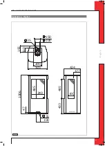
Page 21: ...E n g l i s h TRIO INSTRUCTION FOR INSTALLATION Appendix 4 Figures 340 485 1006 35 47 100 403 485 424 177 160 38c 1218 3 100 150 505 35 155 200 110 Fig 1 21...

Page 22: ...E n g l i s h TRIO INSTRUCTION FOR INSTALLATION Fig 4 Fig 5 Fig 6 Fig 3 1 4m max 3m 38c 744f 1x90 Fig 2 22...

Page 23: ...E n g l i s h TRIO INSTRUCTION FOR INSTALLATION Fig 8 Fig 9 Fig 10 Fig 7 23...

Page 24: ...E n g l i s h TRIO INSTRUCTION FOR INSTALLATION Fig 11 Fig 13 Fig 12 Fig 14 24...

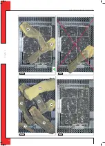
Page 25: ...E n g l i s h TRIO INSTRUCTION FOR INSTALLATION Fig 19 Fig 15 Fig 17 Fig 16 Fig 18 25...

Page 26: ...E n g l i s h TRIO INSTRUCTION FOR INSTALLATION Fig 21 Fig 20 26...

Page 27: ...E n g l i s h TRIO INSTRUCTION FOR INSTALLATION O A B 38C 2031 1 Fig 22 38p 0181 Fig 23 38p 0179 Fig 24 5mV 38p 0182 Fig 25 27...

Page 28: ...DRU Verwarming B V The Netherlands Postbus 1021 NL 6920 BA Duiven Ratio 8 NL 6921 RW Duiven...

Reviews: