English
T R I O
-
I N S T R U C T I O N
F O R
I N S TA L L AT I O N
➠
Remove the top plate from the appliance; this plate is loose;
➠
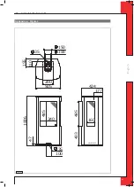
Remove the cover plate by unscrewing the 2 parkers (
see Appendix 4,
Fig. 2
);
➠
Place a lacquered pipe piece on the appliance;
➠
Apply a lacquered clip binding with silicon sealing ring onto the connection between appliance and pipe piece;
➠
Refit the cover plate with the 2 parkers;
➠
Place the top plate carefully onto the appliance, so that the lacquered pipe piece will not be damaged;
➠
If necessary, connect the vertical (lacquered) concentric pipe pieces;
➠
Connect the lacquered bend;
➠
If necessary, connect the horizontal (lacquered) concentric pipe pieces;
➠
On each connection, apply a (lacquered) clip binding with silicon sealing ring;
➠
Use a parker to fix the clip binding to the pipe on locations that are unreachable after installation;
➠
Attach the concentric system with sufficient fastening brackets, so that the weight is not resting on the appliance.
Observe the following;
- Place the first fastening bracket 0.5 metre from the appliance, at the most.
-
Place a fastening bracket maximum 0.1 metre from each bend, if the bends are more than 0.25 metre away from
each other. If two bends are closer to one another than 0.25 metre, 1 fastening bracket between these bends will be
sufficient.
- At least every 1 metre, place a fastening bracket at slanted and horizontal sections.
- At least every 2 metres, place a fastening bracket at vertical sections.
➠
Determine the remaining length of the wall duct;
➠
Make sure the wall duct has the right dimensions.
!Caution
-
Make sure that the right insertion length is maintained;
-
Place the wall duct with the groove/folded seam at the top;
-
Make sure the horizontal concentric pipe pieces are sloping towards the wall duct, in order to prevent rain water
from entering.
➠
Mount the rosette (mounting inner plate); if necessary, on a heat resistant intermediate plate when passing through
combustible material;
➠
Attach the wall duct from the outside with four screws in their respective holes.
6.5.3 Application with roof duct
6.5.3.1 Construction of concentric system with roof duct
The concentric system with roof duct has to comply with the following conditions:
- The construction of the chosen system has to be allowed. (See the procedure described below);
- First, a concentric pipe of at least 1 meter should be connected vertically to the appliance.
Depending on the construction, the appliance is set by means of the baffle and/or the air inlet guide.
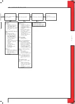
In the following procedure you can see how the allowability of a concentric system can be determined and which
settings are needed.
➠
Determine the following data:
1) The number of bends required (no distinction is made between 45° and 90° bends);
2) The total number of meters of horizontal pipe length;
3) The total number of meters of vertical and/or sloping pipe length.
These data will help you determine whether the concentric system is allowed by using Table 1 for G25/G25.3 and
Table 3 for G20.
In Table 2 you can read for G25/G25.3 and G20 which setting is required for the appliance.
Follow the procedure described below:
➠
In the first 2 columns of Table 1/Table 3, search the number of bends required and the total horizontal pipe length:
➠
In the 3rd column of Table 1/Table 3, search the total vertical and/or sloping pipe length.
If you end up in a box with the letter A, B, C, D or E, the concentric system chosen by you is allowed.
➠
Use Table 2 to determine which conditions apply for the baffle and/or the air inlet guide (for placing/setting see section 6.7).
Examples G25/G25.3
To clarify, we will give 2 examples for gas G25/G25.3, to determine the allowability of a concentric system and the
conditions for setting the appliance.
In Table 1 the route to be followed is indicated by arrows. The result is indicated by an underlined letter (= allowed)
or a dash “-“ (= not allowed).
6
Summary of Contents for Trio RCE G20
Page 23: ...E n g l i s h TRIO INSTRUCTION FOR INSTALLATION Fig 8 Fig 9 Fig 10 Fig 7 23...
Page 24: ...E n g l i s h TRIO INSTRUCTION FOR INSTALLATION Fig 11 Fig 13 Fig 12 Fig 14 24...
Page 25: ...E n g l i s h TRIO INSTRUCTION FOR INSTALLATION Fig 19 Fig 15 Fig 17 Fig 16 Fig 18 25...
Page 26: ...E n g l i s h TRIO INSTRUCTION FOR INSTALLATION Fig 21 Fig 20 26...
Page 28: ...DRU Verwarming B V The Netherlands Postbus 1021 NL 6920 BA Duiven Ratio 8 NL 6921 RW Duiven...


