English
T R I O
-
I N S T R U C T I O N
F O R
I N S TA L L AT I O N
!Caution
Some heat-resistant isolation materials contain volatile components that will spread an unpleasant smell for a pro-
longed time; these are not suitable.
➠
Remove the top plate from the appliance; this plate is loose;
➠
Remove the cover plate by unscrewing the 2 parkers (
see Appendix 4,
Fig. 3
);
➠
Place a lacquered pipe piece on the appliance;
➠
Apply a lacquered clip binding with silicon sealing ring onto the connection between appliance and pipe piece;
➠
Refit the cover plate with the 2 parkers;
➠
Place the top plate carefully onto the appliance, so that the lacquered pipe piece will not be damaged;
➠
Connect the horizontal (lacquered) concentric pipe pieces and, if necessary, the bends;
➠
On each connection, apply a (lacquered) clip binding with silicon sealing ring;
➠
Use a parker to fix the clip binding to the pipe on locations that are unreachable after installation;
➠
Attach the concentric system with sufficient fastening brackets, so that the weight is not resting on the appliance.
Observe the following;
- Place the first fastening bracket 0.5 metre from the appliance, at the most.
-
Place a fastening bracket maximum 0.1 metre from each bend, if the bends are more than 0.25 metre away from
each other. If two bends are closer to one another than 0.25 metre, 1 fastening bracket between these bends will be
sufficient.
- At least every 1 metre, place a fastening bracket at slanted and horizontal sections.
- At least every 2 metres, place a fastening bracket at vertical sections.
➠
Fasten a roof terminal with anchor cables, if it protrudes more than 1,5 metres above the terminal.
➠
Determine the remaining length of the roof duct;
➠
Make sure the roof duct has the right dimensions.
!Caution
Make sure that the right insertion length is maintained.
➠
Connect the roof duct to the concentric pipes.
!Caution
-
Make sure that the universal tile fits well with the surrounding tiles;
-
Make sure that the adhesive plate fits well onto the flat roof.
6.5.4 Connection of existing chimney flue
It is possible to connect the appliance to an existing channel.
A flexible SS pipe is placed in the chimney for discharging flue gases. The surrounding space is used to supply
combustion air.
The following requirements apply when connecting to an existing chimney flue:
- only allowed when used in combination with the special DRU chimney installation set.
The installation regulation is also supplied;
- the dimensions should be at least 150 x 150 mm;
- the vertical length has a maximum of 12 meters;
- the horizontal length has a maximum of 3 meters;
- the existing chimney flue has to be clean;
- the existing chimney flue has to be closed.
For adjusting the appliance, the same conditions/instructions apply as for the concentric system described above.
6.6 Connecting gas
Use the following procedure when connecting the gas, see section 6.3 Gas connection:
➠
If necessary, blow through the gas pipe;
➠
Connect the gas pipe with gas tap to the gas control block.
!Caution
-
You can find the gas control block behind the door in the space at the bottom of the appliance;
-
Do not turn the gas tap when connecting the gas pipe.
➠
Bleed the gas pipe.
6.7 Setting the appliance
The appliance has to be set in such a way that is works correctly in combination with the discharge system.
For that purpose it is possible to install a baffle and/or an air inlet guide. For the conditions, see section 6.5.2.1,
for application with wall duct and section 6.5.3.1, Table 2, for application with roof duct.
6.7.1 Baffle (R)
!Caution
The restrictor slide should be placed in the correct manner. Therefore, accurately observe the instructions
The baffle (R) is supplied separately.
Follow the procedure below when placing the baffle:
➠
Remove the front pane as indicated in section 6.9.1;
9
Summary of Contents for Trio RCE G20
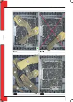
Page 23: ...E n g l i s h TRIO INSTRUCTION FOR INSTALLATION Fig 8 Fig 9 Fig 10 Fig 7 23...
Page 24: ...E n g l i s h TRIO INSTRUCTION FOR INSTALLATION Fig 11 Fig 13 Fig 12 Fig 14 24...
Page 25: ...E n g l i s h TRIO INSTRUCTION FOR INSTALLATION Fig 19 Fig 15 Fig 17 Fig 16 Fig 18 25...
Page 26: ...E n g l i s h TRIO INSTRUCTION FOR INSTALLATION Fig 21 Fig 20 26...
Page 28: ...DRU Verwarming B V The Netherlands Postbus 1021 NL 6920 BA Duiven Ratio 8 NL 6921 RW Duiven...


