background image

6000-300-000

 7–7


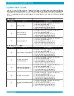
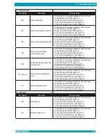
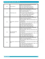
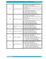
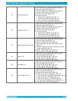
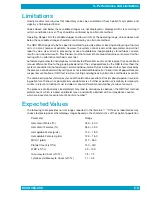
7 – Troubleshooting

E3 - Camera Board

Error Number

Description

Corrective Action

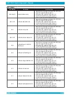
300

Camera board error

1.  Record the error message displayed on the LCD screen
2.  Export the support file (Ref. page 2-8)
3.  Power down the instrument (Ref. page 4-10)
4.  Turn the instrument Power on (Ref. page 4-2)
5.  If the error persists contact Technical Support

301

Camera board device driver error

1.  Record the error message displayed on the LCD screen
2.  Export the support file (Ref. page 2-8)
3.  Power down the instrument (Ref. page 4-10)
4.  Turn the instrument Power on (Ref. page 4-2)
5.  If the error persists contact Technical Support

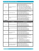
303

Camera board data reading error

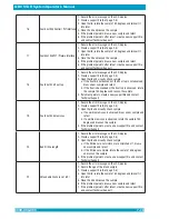
1.  Record the error message displayed on the LCD screen
2.  Export the support file (Ref. page 2-8)
3.  Power down the instrument (Ref. page 4-10)
4.  Turn the instrument Power on (Ref. page 4-2)
5.  If the error persists contact Technical Support

304

Camera board parameter 
communications error

1.  Record the error message displayed on the LCD screen
2.  Export the support file (Ref. page 2-8)
3.  Power down the instrument (Ref. page 4-10)
4.  Turn the instrument Power on (Ref. page 4-2)
5.  If the error persists contact Technical Support

305

Unable to verify commands sent 
to camera error

1.  Record the error message displayed on the LCD screen
2.  Export the support file (Ref. page 2-8)
3.  Power down the instrument (Ref. page 4-10)
4.  Turn the instrument Power on (Ref. page 4-2)
5.  If the error persists contact Technical Support

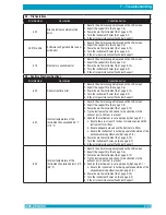
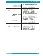
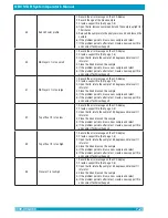
311 thru 316

Camera board communication 
errors

1.  Record the error message displayed on the LCD screen
2.  Export the support file (Ref. page 2-8)
3.  Power down the instrument (Ref. page 4-10)
4.  Turn the instrument Power on (Ref. page 4-2)
5.  If the error persists contact Technical Support

317

Camera initialization error

1.  Record the error message displayed on the LCD screen
2.  Export the support file (Ref. page 2-8)
3.  Power down the instrument (Ref. page 4-10)
4.  Turn the instrument Power on (Ref. page 4-2)
5.  If the error persists contact Technical Support

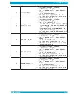
E4 - I/O Board

Error Number

Description

Corrective Action

400

I/O board error

1.  Record the error message displayed on the LCD screen
2.  Export the support file (Ref. page 2-8)
3.  Power down the instrument (Ref. page 4-10)
4.  Turn the instrument Power on (Ref. page 4-2)
5.  If the error persists contact Technical Support

401

Software version error

1.  Record the error message displayed on the LCD screen
2.  Export the support file (Ref. page 2-8)
3.  Power down the instrument (Ref. page 4-10)
4.  Turn the instrument Power on (Ref. page 4-2)
5.  If the error persists contact Technical Support

Summary of Contents for QBC STAR

Page 1: ...ystem Operator s Manual Fast Simple CBC Analysis Designed for the Point of Care Document Number 6000 300 000 Revision J 200 Shady Lane Suite 170 Philipsburg PA 16866 U S A 1 814 692 7661 www druckerdi...

Page 2: ...es to mitigate the interference The electromagnetic environment should be evaluated prior to operation of the QBC STAR Do not use this device in close proximity to sources of strong electromagnetic ra...

Page 3: ...1 6 Symbols Used on the Equipment 1 6 Notes Cautions and Warnings 1 6 Summary of Warnings and Cautions 1 7 2 Installation and Setup 2 1 Unpacking and Setup 2 1 Electrical Connection 2 1 QBC STAR Speci...

Page 4: ...eel 3 3 Setup Keypad 3 4 ESC Key 3 4 5Key 3 4 6Key 3 4 Key 3 4 4 Operation 4 1 Summary of Operation Steps 4 1 Turn Instrument Power On 4 2 Prepare the QBC STAR Tube 4 2 Mix the Tube 4 4 Tilt the Tube...

Page 5: ...Internal Electronic Quality Control Label 5 5 External Liquid Controls 5 6 Proficiency Tests 5 6 6 Maintenance 6 1 Cleaning 6 1 Disinfection 6 1 Replacing Printer Paper 6 2 7 Troubleshooting 7 1 Gener...

Page 6: ...ure Description Page 1 QBC STAR Blood Collection Tube 1 2 2 QBC STAR Instrument 1 3 3 Symbols Used on the QBC STAR Instrument rear 1 6 4 External Connections 2 5 5 QBC STAR Menu Options 2 7 6 QBC STAR...

Page 7: ...ple when it is centrifuged A special coating in the QBC STAR tube stains the two white blood cell populations granulocytes appear orange yellowandlymphocytes monocytesappeargreen andtheplateletlayer p...

Page 8: ...erves as a carrier for the tube A cap and float assembly comprise the second component The float expands the buffy coat region by a factor of ten It does this by reducing the cross sectional area of t...

Page 9: ...eparating the blood into the various cell populations Analysis of the sample occurs in the centrifuge rotor after the centrifuge is finished A single filled QBC STAR Tube is placed into the rotor the...

Page 10: ...a sample is processed Sample integrity checks include statistical matching of bandlengths ratios and absolute values for signal levels ratios that are used to evaluate the quality of interfaces measu...

Page 11: ...llection and bibliography andtheGlossaryexplainsseveraltermsusedinthismanual aswellasabreviations Getting Started The QBC STAR system has been designed and tested for ease of use However before you be...

Page 12: ...ent Conventions Symbols Used on the Equipment The following symbol appears on the QBC STAR instrument Figure 3 Warning symbol Used on the QBC STAR Instrument Notes Cautions and Warnings Throughout thi...

Page 13: ...Y BE TOXIC DO NOT INGEST AVOID CONTACT WITH SKIN EYES AND CLOTHING If a tube breaks in the unit carefully remove the tube with a hemostat or other device using puncture resistantutilitygloves CONTACTD...

Page 14: ...THIS PAGE INTENTIONALLY LEFT BLANK...

Page 15: ...end of the power pack to the back of the QBC STAR instrument see Figure 4 Connect the male end of the power cord to the main AC power source To avoid electrical shock connect the power cord only to a...

Page 16: ...Height loading door open 16 3 in 41 4 cm Width 16 in 40 6 cm Depth 16 3 in 41 4 cm Weight 19 lbs 8 6 kg Clearance 2 in 5 1 cm Noise 70 dB 3 ft 6000 300 000 2 2 Electrical Specifications for the Power...

Page 17: ...unrestricted at 32 C use may be limited by instrument temperature shut down or some results may be suppressed Humidity 10 95 non condensing Surface Inclination 10 any direction without restraint 45 an...

Page 18: ...howninFigure4 DC power input USB Port 3x for external printer keyboard USB memory stick or scanner Ethernet Port You can attach a keyboard USB memory stick barcode scanner and a full size external pri...

Page 19: ...manufacturer s operating instructions 2 Connect the printer to the QBC STAR instrument s USB port see Figure 4 3 Turn on power to the QBC STAR instrument first 4 Turn on power to the external printer...

Page 20: ...from step 4 and step 7 from device and mail to Drucker Diagnostics in Appendix D 1 scan a copy to qbcsupport druckerdiagnostics com or fax to 814 692 7662 DO NOT turn off the device while the software...

Page 21: ...display contrast When you reach the desired contrast press Date and Time The Date and time option lets you adjust the date and time that is printed on results reports When you select the option a sub...

Page 22: ...the Printer Settings option a sub menu titled Printer Settings appears Enable Disable External Printer When the printer is ENABLED the menu lets you disable the printer by selecting option 4 External...

Page 23: ...option allows you to select whether certain results are reported in SI units Millimoles per liter or STD units Grams per deciliter The results that are affected are hemoglobin and MCHC When STD Units...

Page 24: ...ghts etc are described below The following items are discussed Power Switch STAR Button Door Release Latch Liquid Crystal Display Printer Setup Keypad Power Switch The power switch is located on the r...

Page 25: ...e door It is used to open the door on the top of the instrument The door can only be opened when the system determines that it is safe to do so The door is locked electromechanically when it is unsafe...

Page 26: ...ease Lever The paper release lever is located on the right side of the printer Pull the lever forward to enable loading paper When the lever is forward the manual advance wheel below is operational Pu...

Page 27: ...e LCD contrast etc The setup keypad keys Figure 10 are described below Setup functions are described in Section 2 Installation and Setup ESC Key Press this key to cancel an action or to return to a pr...

Page 28: ...THIS PAGE INTENTIONALLY LEFT BLANK...
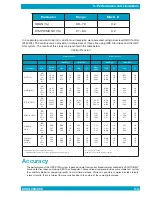
Page 29: ...ORANGE REAGENT MAY BE TOXIC DO NOT INGEST AVOID CONTACT WITH SKIN EYES AND CLOTHING IF A TUBE BREAKS IN THE UNIT CAREFULLY REMOVE THE TUBE WITH A HE MOSTAT OR OTHER DEVICE USING PUNCTURE RESISTANT UTI...

Page 30: ...is displayed When the self test is complete and the system is ready the following message appears on the LCD readout Ready Insert Sample Close Door Press Note that if power is left on continuously an...

Page 31: ...ayer away For Venous Blood Samples 1 Gently mix the sample by inverting the capped sample vial 12 15 times immediately before filling the tube as shown in Figures 11 and 12 2 After mixing tilt the sam...

Page 32: ...he black fill lines Blood must always be filled to at least the first black line This results in a blood volume of between 65 and 75 microliters The instrument automatically detects if the fill volume...

Page 33: ...p from the tube by pulling it straight off Ensure that the blood is centered in the tube before placing the cap on the tube Place the cap over the collection end of the tube by guiding the glass end o...

Page 34: ...nsert the tube is to first place the capped end into place then pivot the uncapped end of the tube down into the recessed area If the capped end is not seated correctly the tube will not pivot down in...

Page 35: ...es the blood and reagents in the tube A countdown displays the time remaining in the cycle After mixing is complete the centrifuge accelerates to high speed to separate and pack the cell populations i...

Page 36: ...Parameter abbreviation STD Units SI Units Hematocrit Hct Percentage Percentage Hemoglobin Hgb g dL mMol L Mean Corpuscular Hemoglobin Concentration MCHC g dL mMol L White Blood Cells WBC 109 L 109 L...

Page 37: ...Results Printout Figure 21 Sample Results Readout 6000 300 000 4 9 6000 300 000 4 9 4 Operation Any errors that might occur are both displayed and printed on the results printout Test results are prin...

Page 38: ...curs or the unit breaks down If this occurs a message appears on the LCD display Emergency Door Unlock In the event of a power failure or the failure of certain components you may be unable to open th...

Page 39: ...6000 300 000 4 11 4 Operation Door Latch Access Hole Front of Instrument Bottom of Instrument Figure 22 Door Unlatch Access Hole 6000 300 000 4 11...

Page 40: ...QBC STAR System Operator s Manual 6000 300 000 4 12 THIS PAGE INTENTIONALLY LEFT BLANK...

Page 41: ...Count 0 8 99 9 x 10⁹ L Lymph Mono 1 99 Results that fall outside these ranges may be confirmed by alternate methods 6000 300 000 5 1 As a reference the STAR will display the numerical values of some p...

Page 42: ...99 If either Gr or LM is in this range and if both Gr and LM have numeric values If either Gr or LM or both is in this range The table below listed the ranges between Operating Ranges the ranges that...

Page 43: ...20 19 LYMPH MONO x 109 L BD POL 1 POL 2 4 38 4 48 4 26 1 49 0 00 5 35 10 10 9 5 62 6 52 6 56 20 20 19 15 81 15 44 14 52 0 00 1 75 7 63 10 10 9 8 96 7 59 12 61 20 20 19 Variability between runs during...

Page 44: ...y The QBC STAR software has been calibrated to match the interna tional reference standard for microhematocrit MHCT technology The data shown in the table below was obtained by comparing the QBC STAR...

Page 45: ...s by the QBC test method the system cannot discriminate between normal and abnormal cell types in disease states characterized by the presence of abnormal white cell types or nucleated red blood cells...

Page 46: ...ulating low cell counts normal cell counts and elevated cell counts tests the system s optics against values established at the time of manufacture At the end of the power on self test the instrument...

Page 47: ...the rotor into a free spinning state 2 Understanding Results and Errors During QBC Star system startup or daily POST check the tri level quality control label QC label is read and analyzed When an er...

Page 48: ...until the QC label is visible in the operator accessible opening on the front of QBC Star Do not apply excessive pressure to the rotor surface or damage could occur 3 Gently wipe the label surface wit...

Page 49: ...mmerse the QBC STAR instrument in water or other liquid Replacing Printer Paper When the printer paper is nearly exhausted a colored edge appears on the roll of paper You should replace paper at this...

Page 50: ...THIS PAGE INTENTIONALLY LEFT BLANK...
Page 51: ...ing on bottom of instrument Call Technical Support Lid fails to open Power has failed Use emergency door unlock procedure in Section 4 Defective lid solenoid or internal parts Request authorized servi...

Page 52: ...rd the error message displayed on the LCD screen 2 Export the support file Ref page 2 8 3 Power down the instrument Ref page 4 10 4 Turn the instrument Power on Ref page 4 2 5 If the error persists co...

Page 53: ...the support file Ref page 2 8 3 Power down the instrument Ref page 4 10 4 Turn the instrument Power on Ref page 4 2 5 If the error persists contact Technical Support 217 Centrifuge motor index error...

Page 54: ...e 7 1 5 Turn the instrument Power on Ref page 4 2 6 If the error persists contact Technical Support 252 Centrifuge control board unable to process seek command error 1 Record error message displayed o...

Page 55: ...per Section 4 page 4 10 4 Turn Instrument Power on per Section 4 page 4 2 if error persists contact Technical Support 265 Centrifuge motor encoder mismatch error 1 Record error message displayed on LC...

Page 56: ...fuge control board internal temperature sensor initialization error 1 Record error message displayed on LCD screen 2 Export support file per Section 2 page 2 8 3 Power down instrument per Section 4 pa...

Page 57: ...o verify commands sent to camera error 1 Record the error message displayed on the LCD screen 2 Export the support file Ref page 2 8 3 Power down the instrument Ref page 4 10 4 Turn the instrument Pow...

Page 58: ...rinter paper release lever to lock the paper into place Ref page 3 3 6 Power down the instrument Ref page 4 10 7 Turn the instrument Power on Ref page 4 2 8 If the error persists contact Technical Sup...

Page 59: ...LCD screen 2 Export the support file Ref page 2 8 3 Power down the instrument Ref page 4 10 4 Turn the instrument Power on Ref page 4 2 5 If the error persists contact Technical Support 411 thru 414...

Page 60: ...ort the support file Ref page 2 8 3 Power down the instrument Ref page 4 10 4 Tip the instrument up and check for obstructions in the exhaust port 5 If there are obstructions clear the obstructions an...

Page 61: ...age 4 2 5 If the error persists contact Technical Support 601 Internal temperature of the instrument has exceeded 45 C 113 F 1 Record the error message displayed on the LCD screen 2 Export the support...

Page 62: ...he LCD screen 2 Export the support file Ref page 2 8 3 Power down the instrument Ref page 4 10 4 Turn the instrument Power on Ref page 4 2 5 If the error persists contact Technical Support 701 Power O...

Page 63: ...2 Export the support file Ref page 2 8 3 Power down the instrument Ref page 4 10 4 Turn the instrument Power on Ref page 4 2 5 If the error persists contact Technical Support 708 Power On Self Test P...

Page 64: ...support file Ref page 2 8 3 Power down the instrument Ref page 4 10 4 Turn the instrument Power on Ref page 4 2 5 If the error persists contact Technical Support 808 Software fault handling error 1 R...

Page 65: ...the error message displayed on the LCD screen 2 Export the support file Ref page 2 8 3 Power down the instrument Ref page 4 10 4 Turn the instrument Power on Ref page 4 2 5 If the error persists conta...

Page 66: ...cord the error message on the LCD display 2 Create a support file Ref page 2 8 3 Open the lid rotate the sample 180 degrees and reinsert it into the rotor 4 Close the lid and rescan the sample 5 If th...

Page 67: ...aw a new sample and retest 6 If the problem persists after retest create a new support file and contact Technical Support 13 Could not find Grans LM interface 1 Record the error message on the LCD dis...

Page 68: ...ate the sample 180 degrees and rescan the sample 4 If problem persists create a new support file and contact Technical Support 19 Could not find meniscus 1 Record the error message on the LCD display...

Page 69: ...es and reinsert it into rotor 4 Close the lid and rescan the sample 5 If the problem persists draw a new sample and retest 6 If the problem persists after retest create a new support file and contact...

Page 70: ...he sample 5 If the problem persists draw a new sample and retest 6 If the problem persists after retest create a new support file and contact Technical Support 52 Top of float I7 is too low 1 Record t...

Page 71: ...oat 1 Record the error message on the LCD display 2 Create a support file Ref page 2 8 3 Open the lid rotate the sample 180 degrees and reinsert it into rotor 4 Close the id and rescan the sample 5 If...

Page 72: ...6000 300 000 A 1 8 Appendices 6000 300 000 8 1...

Page 73: ...agnostics Inc It is understood that the equipment covered by this agreement has been installed in accordance with the recommendations and instructions in the QBC STAR System Operator s Manual Any dama...

Page 74: ...THIS PAGE INTENTIONALLY LEFT BLANK...

Page 75: ...8 mm Blade Lancets box 100 420000 2 3 mm Blade Lancets box 100 420001 Patient ID Upgrade Keyboard 429645 Patient ID Barcode Scanner 429642 Power Cord U K 421554 Power Cord Europe 421551 Power Cord US...

Page 76: ...THIS PAGE INTENTIONALLY LEFT BLANK...

Page 77: ...SA www druckerdiagnostics com Phone 1 814 692 7661 Technical Support 1 866 265 1486 USA only Customer Service 1 877 231 3115 USA only Fax 1 814 692 7662 Email Technical Service qbcsupport druckerdiagn...

Page 78: ...THIS PAGE INTENTIONALLY LEFT BLANK...

Page 79: ...software upgrade please take a moment to log it below This can assist you and Drucker Diagnostics personnel in identifying software revision levels potential software problems etc Date Received Softw...

Page 80: ...THIS PAGE INTENTIONALLY LEFT BLANK...

Page 81: ...ument POL1 and POL2 For more information contact NCCLS at 771 East Lancaster Avenue Villanova PA 19085 215 525 2435 Universal Precautions for Specimen Handling WARNINGS BLOOD AND BODY FLUIDS MAY CONTA...

Page 82: ...d Have the patient make a fist but avoid vigorous pumping or other hand exercise 5 Apply the tourniquet about 3 4 inches above the venipuncture site Do not stop the blood flow for more than one minute...

Page 83: ...stopped and apply a bandage over the site Instruct the patient to wear the bandage for at least 15 minutes i Gently invert any tube s containing anticoagulant or clot activators as in SST Brand tubes...

Page 84: ...name 2 Select and organize the appropriate blood collection supplies 3 Select a puncture site With older children and adults use the third or fourth finger of the non dominant hand Choose a puncture...

Page 85: ...od Collection Allow the puncture site to dry after cleaning with alcohol Do not squeeze the puncture site excessively Do not press or scrape the collection device on the skin To avoid clotting in capi...

Page 86: ...THIS PAGE INTENTIONALLY LEFT BLANK...

Page 87: ...Fluorescence Blood 17 643 17 643 649 7 Wardlaw S C and Levine R A Quantitative Buffy Coat Analysis JAMA 5 617 620 1983 8 Data on file at Becton Dickinson Biosciences Division Sparks MD 21152 9 Young...

Page 88: ...n 1g acceleration of gravity Gran Granulocytes Hgb Hemoglobin Hct Hematocrit L M Lymphocytes and Monocytes Lymph Monos Lymphocytes and Monocytes MCHC Mean Corpuscular Hemoglobin Concentration Plt Plat...

Page 89: ...THIS PAGE INTENTIONALLY LEFT BLANK...

Reviews: