Setup (CME)
Primary “HTF” Circulation Lines
•
If possible, position the primary circulation lines out of high traffic areas.
•
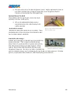
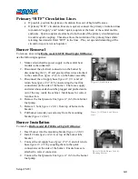
If primary “HTF” circulation lines are required, connect the primary circulation lines
to manifold “supply” and “return” quick couplers at the back of the central mobile
enclosure. Quick couplers are attached to both ends of the primary circulation lines
to enable quick coupling. This also allows the isolation of the primary lines while
retaining heat transfer fluid “HTF” in the lines. Plus, set up and dismantling of the
circulation system is much quicker.
Burner Removal
To remove an existing
Riello model 40-F20 Diesel/Light Oil Burner
,
use the following sequence:
1.
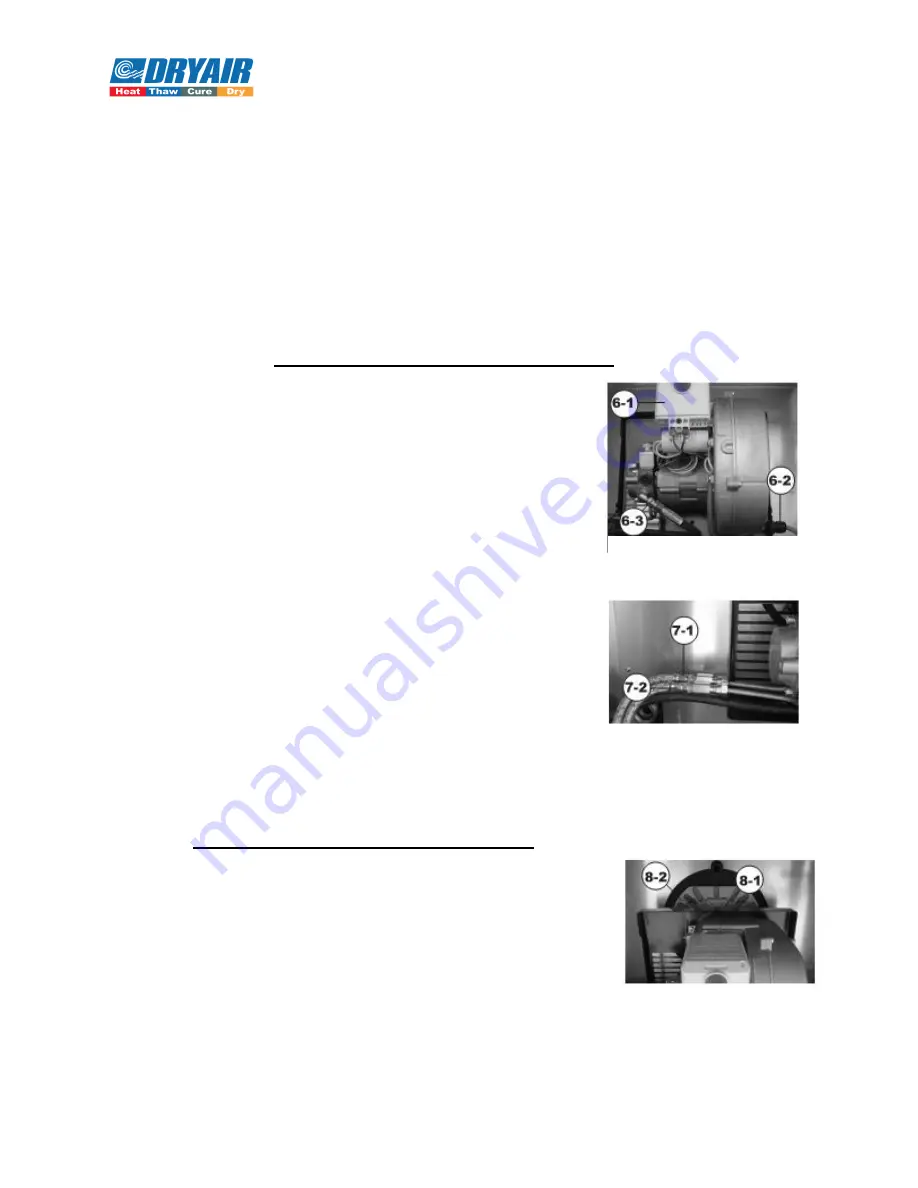
Make certain that the power supply to the central heat
module is disconnected.
2.
Disconnect the electrical connection to the burner by
disconnecting the #1, #2 and green/yellow wires attached
to the control box
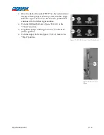
figure 12
(6-1) on the burner assembly.
3.
Disconnect the oil supply hose
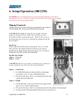
figure 13
(7-1) and oil
return hose
figure 13
(7-2) by unscrewing the fuel line
connections on the side of the burner. The loose supply
and return hose ends should be plugged and pushed aside
out of the way inside the cabinet. Mark hoses for correct
reconnection.
4.
Remove the fuel pressure line
figure 12
(6-3) from burner
fuel pump.
5.
Remove 2 bolts
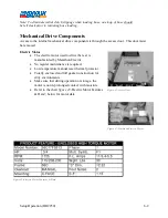
figure 14
(8-1) from top of burner tube
bracket.
6.
Pull burner towards you and away from the mounting
bracket
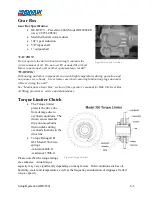
figure 14
(8-2).
Burner Installation
To install a
Riello model 40-F20 Diesel/Light Oil Burner
:
1.
Insert burner into the mounting bracket
figure 14
(8-2).
2.
Install 2 bolts
figure 14
(8-1) at top of the burner tube
bracket.
3.
Connect the oil supply hose
figure 13
(7-1) and oil return
hose
figure 13
(7-2) by coupling them to the quick
connections on the side of the burner. Ensure hoses are
attached to correct connectors.
4.
Connect the fuel pressure line
figure 12
(6-3) to the burner
fuel pump.
Figure 12-Riello Burner
Figure 13-Oil Supply and Return
Lines
Figure 14-Oil Supply and Return
Lines
Figure 14-Riello Burner Tube &
Mounting Bracket
4-4
Summary of Contents for 600 GTS Series
Page 2: ......
Page 47: ...Appendix 9 3 Electrical Schematics Figure 56 600 GTS sub 40 Electrical Schematic...
Page 48: ...Appendix 9 4 Figure 57 600 GTS Electrical Schematic...
Page 49: ...Appendix 9 5 Figure 58 HR2250 Electrical Schematic...
Page 50: ...Appendix 9 6 Figure 59 Trailer Wiring Schematic...

