Setup (CME)
4-1
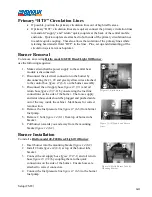
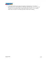
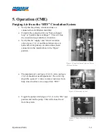
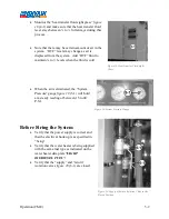
4. Setup (CME)
The positioning of all the
system components on the site
will be influenced by several
factors. Please read all the
“Setup” section before
beginning.
Be sure to observe all local
electrical codes and fire
regulations when positioning
the central heating module.
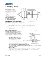
Required Safety Clearances
The 600 GTS is a heating appliance, therefore safe heat
and exhaust clearances must be observed from combustible materials and for service access.
•
Maintain 24” (61cm) of clearance on all sides of the unit
figure 8
(1-1).
•
Maintain 36” (91cm) of clearance
figure 9
(2-1) on all sides of the flue pipe and
chimney cap.
Elevation Concerns
Do not place any “portable heat exchangers”
or “circulation line heat exchangers” higher
than the top-level
figure 9
(2-2) of the heat
transfer fluid fill tank. If this is not observed,
the following can occur:
•
Insufficient fluid in the system.
Fluid will drain back to the heat
transfer fill tank from the over-
elevated fluid lines when the pump
is shut off. The heat transfer fill
tank will show adequate fluid, but when the pump is
started extra fluid will be required to recharge the over-
elevated fluid lines and portable heat exchangers and the system will have insufficient
fluid in the reservoir.
•
Fluid overflow.
If fluid is added to maintain proper fluid levels while the pump is running, overflow
at the fill tank will occur when the pump is shut off. This would occur because of
drain back from the over-elevated fluid lines.
Figure 8-600 GTS Top View
Figure 9-600 GTS Side View
Summary of Contents for 600 GTS Series
Page 2: ......
Page 47: ...Appendix 9 3 Electrical Schematics Figure 56 600 GTS sub 40 Electrical Schematic...
Page 48: ...Appendix 9 4 Figure 57 600 GTS Electrical Schematic...
Page 49: ...Appendix 9 5 Figure 58 HR2250 Electrical Schematic...
Page 50: ...Appendix 9 6 Figure 59 Trailer Wiring Schematic...


