background image

HOT PRESS USERS MANUAL

5

Press Set Up

stand. Undo catches at front of press and raise lid. Remove three screws 

at  front  of  diaphragm  and  draw  diaphragm  forward  by  approximately 

300  mm  or  12  inches.  Working  on  underside  of  diaphragm,  remove 

hoses from fi ttings on diaphragm by pushing collar on hose end of fi tting 

inwards and pulling out hose. Remove diaphragm from press. Using the 

4 M6 x 80 mm bolts, 8 M6 penny washers, 4 M6 spring washers and 4 

M6 nuts, secure the press to the stand by passing the bolts up through 

the holes in the stand ends and into the base of the press.  Tighten these 

nuts and bolts. Insert the diaphragm back into the press and unsert the 

hoses back into the fi ttings on the underside of the diaphragm.

Push the diaphragm back into position ensuring it fi ts into the three 

clips at the back of the press and re-fi t the three screws at the front of 

the diaphragm.

Stand Assembly Instructions for Small Models

(HGP220 / 260/ 36

0)

Component list:


• 2 x leg assemblies


• 2 x top rails


• 2 x bottom rails


• 12 x rail bolts (16 x for 360) M8 x 60 mm dome head


• 4 x press fi xing bolts M6 x 80 mm cap head


• 4 x penny washers ¼ x 1 “


• 4 x shakeproof washers M6


• 1 x M6 Allen key

Loosely fi t the top rails to the top of the leg assemblies to form a rectangle, 

using 8 of the M8 x 60 mm bolts. Loosely fi t the bottom rails, about half 

way up the leg assemblies, using the remaining M8 x 60 bolts. Tighten 

all bolts using the Allen key and ensure stand is steady. The top rails are 

inset from the front and rear, the largest inset is the front of the stand. Lift 

press onto stand. Fit M6 x 80 mm bolts with shakeprooof washers, then 

with the penny washers, then insert them up through the leg assemblies 

into the base of the press. Tighten press fi xing bolts using the Allen key, 

until rubber press feet are compressed slightly.

Connecting the Vacuum Pump

A length of plastic vacuum tubing (either red or green, depending on 

the model) is supplied with the equipment. Connect one end to the 

pump and the other end to the rear of the vacuum press. No tools are 

needed - the tubing is a simple “push fi t” into the special connectors.  

You will feel two stages of resistance as the tube is inserted. The ends 

of  the  tubing  must  be  clean  and  smooth  to  ensure  a  good  seal.  If 

damaged, simply cut off 1/4” (5mm) with a sharp knife. To remove the 

tubing, press the end of the metal fi tting and pull the tubing out.

Plug the electrical cord from the pump into the matching connector on 

the rear of the vacuum press.

Illustration 5A:

 Vacuum pump 

connections .

THE CORRECT FUNCTIONING OF 

YOUR VACUUM PRESS CANNOT 

BE GUARANTEED IF THE PRESS 

IS NOT MOUNTED SECURELY 

ONTO THE STAND

AND THE PRESS LEVELLED

.

WARNING

THIS OPERATION

SHOULD BE CARRIED 

OUT BY A MINIMUM

OF SIX PEOPLE.

WARNING

Summary of Contents for HOT PRESS HGP220

Page 1: ...M PRESS USERS MANUAL This users manual applies to the following Hot Press models HGP220 25 x 37 635mm x 940mm HGP260 35 x 47 890mm x 1194mm HGP360 42 5 x 66 5 1080mm x 1689mm HGP560 50 25 x 98 25 1276mm x 2496mm Model Working Area Revised 7 30 05 ...

Page 2: ...an be viewed throughout most bonding processes The glass is extremely smooth and scratch resistant The Hot Press Glass Top Press handles a wide range of presentation materials from foam board and wood to photos art prints and delicate fabrics The Hot Press brand is well regarded by picture framers and other finishing professionals for its ability to produce consistent high quality results All model...

Page 3: ...talled in a location which allows the lid to be completely raised without interference If the lid is only partially opened it may close unexpectedly Before each use the struts should be checked to be sure they are operating properly Over a period of time the struts will lose pressure and will eventually require replacement The inner surface of the glass top is very hot during normal operation Be v...

Page 4: ...f the unit Unpack and remove the vacuum pump from its box The pump should be placed on or near the floor There are suction cups on the bottom of the pump to help keep it in place since the pump vibrates during operation The pump will become warm during extended usage If the equipment is going to be used in a high volume production environment please allow for adequate ventilation of the area where ...

Page 5: ... x 60 mm bolts Loosely fit the bottom rails about half way up the leg assemblies using the remaining M8 x 60 bolts Tighten all bolts using the Allen key and ensure stand is steady The top rails are inset from the front and rear the largest inset is the front of the stand Lift press onto stand Fit M6 x 80 mm bolts with shakeprooof washers then with the penny washers then insert them up through the l...

Page 6: ...oes not present a hazard Protect the cord at all times from sharp objects hot surfaces oil and chemicals Avoid kinking the cord Periodically inspect the cord and plug and replace immediately if worn or damaged Disconnect the equipment from the power source before moving or servicing Test the GFCI Ground Fault Circuit Interrupter circuit breaker It is the circuit breaker located nearest to the cent...

Page 7: ...nel is in the AUTO position and Manual that the power switch is in the OFF position Connect the power cord to the electrical outlet Remove any materials from inside the press then close and latch the lid Turn the Pressure Adjustment Knob fully clockwise maximum vacuum Turn on the power switch on the front of the press The displays on the Timer and Timer and Timer Temperature controllers should lig...

Page 8: ... 239 F The factory preset temperature is 194 F ADJUSTING THE TEMPERATURE CONTROLLER CELSIUS To adjust the preset temperature press Button 1 and L1 will appear for one second Then press Button 3 to increase or Button 3 to increase or Button 3 Button 4 to decrease the preset temperature Once the desired level is reached press Button 1 to set your required temperature When current is flowing through t...

Page 9: ... press Button 3 to start the Button 3 to start the Button 3 cycle The timer will indicate that the pump is on and begin to count down Once the preset time has elapsed the pump will stop the vacuum will be released and the counter will return to showing the preset time If you wish to stop the cycle part way through simply press Button 4 This will stop the pump release the vacuum and reset the timer...

Page 10: ...well This factor works in conjunction with temperature to create a permanent bond between materials Assuming that the temperature setting of the press is sufficient to activate the adhesive it is almost always preferable to increase dwell rather than temperature Dwell time is set using the Timer page 9 and dictates the vacuum cycle see Pressure below Pressure Pressure is established in the press by...

Page 11: ...etween two sheets of release paper film for approximately 30 seconds to 3 minutes from the time the press has achieved the desired pressure setting Your actual settings will vary according to the size of the press type of dry mounting tissue the type of mounting substrate the artwork material used in terms of material and the size of the print See individual product specifications for recommended dw...

Page 12: ...aminate on top exposed adhesive edge down While holding it firmly on the table with one hand gently pull the release paper away and toward you from underneath 4 Check that there is no dirt or dust trapped under the laminating film If necessary the film may be gently lifted the contaminants removed and the film repositioned 5 Using a burnishing pad or soft cloth lightly smooth the laminating film down o...

Page 13: ...uld simply be wiped with a TacCloth to remove dust particles MAT BOARDS MILL BOARDS To prepare mat board or millboard for mounting use the Anti Static Wisk brush to remove dust particles and other debris HARDBOARD E G MEDIUM DENSITY FIBERBOARD MASONITE ETC To prepare hardboard substrates for mounting wipe down the surface with a TacCloth Should the surface contain irregularities use sandpaper to r...

Page 14: ...ing threaded shaft Adjust only one turn at a time Lengthening the amount of threaded shaft visible by turning counterclockwise will tighten the latch and shortening the amount by turning clockwise will loosen it Overtightening the latches will not improve the effectiveness of the vacuum seal and will cause the latches to wear out prematurely Hinge Adjustment The hinges at the rear of the press are...

Page 15: ...e press Refer to the Routine Maintenance section on page 14 for the procedure A gap at the front of the press may also indicate that the latches need to be adjusted The latches should snap shut with a firm click but should not be difficult to close If they are too loose follow the adjustment procedure in the maintenance section Do not overtighten the latches as this will cause them to wear out prema...

Page 16: ... is not check the circuit breaker at the building s electrical distribution panel Unplug the power cord and check the fuses on the left side of the unit 2 Press starts up normally then overheats and shuts off or the temperature controller displays an error code such as PFA or LOR There is a problem with the temperature controller or temperature sensor Contact Drytac for assistance with repairs 3 V...

Page 17: ...x 98 25 in 1276mm x 2496mm Time to Vacuum HGP220 HGP260 20 seconds typical HGP360 HGP560 30 seconds typical Time to Temperature HGP220 HGP260 HGP360 12 minutes typical HGP560 15 minutes typical Voltage All Models 220 240VAC Single Phase 50 60Hz Power Consumption maximum HGP220 2 3 kW HGP260 2 5 kW HGP360 4 2 kW HGP560 5 75 kW Current nominal maximum HGP220 10 11 Amps HGP260 11 13 Amps HGP360 18 22...

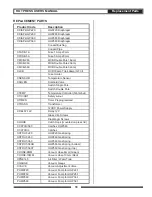
Page 18: ...Pump for HGP220 PUMP260 Vacuum Pump for HGP260 PUMP360 Vacuum Pump for HGP360 PUMP560 Vacuum Pump for HGP560 REPLACEMENT PARTS XDIAP HGP220 HGP220 Diaphragm XDIAP HGP260 HGP260 Diaphragm XDIAP HGP360 HGP360 Diaphragm XDIAP HGP560 HGP560 Diaphragm Conduit Bushing Conduit Pipe XFUSE 1A Fuse 1 Amp 20mm XFUSE 5A Fuse 5 Amp 20mm XMCB 260 MCB Double Pole 16amp XMCB 360 MCB Double Pole 20amp XMCB 560 MCB...

Page 19: ...period has elapsed Drytac will provide all reasonable assistance and will maintain stock of replacement parts This will ensure that any problems that arise can be resolved quickly and economically Please feel free to contact Drytac if you have any questions or problems When calling please have the following information ready Press Model Serial Number found on plate on left side of press Date of Pu...

Reviews: