background image

18

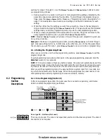
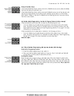
Zone type 01 – Instant alarm for 2-wire smoke detectors and contact devices

Zone type 01 does not differentiate between 2-wire smoke detectors, contact devices, or 4-
wire smoke detectors. When a 2-wire smoke detector, 4 –wire smoke detector or contact 
device goes into alarm:

 1. The panel goes into alarm without any delay. If an instant zone goes into alarm, any auto-

verify sequence in progress on another zone will be immediately cancelled and both zones 
will indicate an alarm condition.

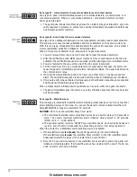
Zone type 02 - Auto-Verify for 2-wire smoke detectors 

Zone type 02 can distinguish between 2-wire smoke detector activation and contact activation. 
This allows you to have manual pullstations and smoke detectors on the same 2-wire zone. 
With this zone type, smoke detector activation starts the auto-verify sequence, and a contact 
closure (pullstation activation) initiates an immediate alarm.

When a 2-wire smoke detector on an auto-verify zone goes into alarm:

 1. Power is removed from the zone for 25 seconds to reset the smoke detector(s).

 2. After the verification period starts (power removed) if any contact device on that zone is 

activated, the verification sequence is cancelled, and the panel goes into immediate alarm. 

 3. Power is restored to the zone at the end of the 25 second reset period. 
 4. For the next 95 seconds, any smoke detector or contact device that goes into alarm will 

cause the panel to immediately go into alarm, activate the NACs, the visual indicators and 
the common alarm relay. 

 5. If during the total verification period (120 sec.), any other zone on the panel goes into 

alarm, the verification sequence is cancelled and the panel immediately goes into alarm. 

 6. If two auto-verify zones activate simultaneously, both verification sequences are cancelled 

and the panel immediately goes into alarm.

When a contact alarm initiating device (pullstation) on an auto-verify zone goes into alarm:

 1. The panel immediately goes into alarm. Any auto-verification sequence that may be active 

will be cancelled.

Zone type 03 – Waterflow zone

This zone type is intended for waterflow alarm initiating contact devices only. Do not mix other 
alarm initiating devices on this zone. You can set the panel to include a fixed timer that will 
delay all ‘Waterflow’ type zone alarms for 60 seconds.

CAUTION: Do not use the waterflow delay timer when:

• The monitored Waterflow alarm actuating devices have a built-in delay of 30 seconds or

more. The overall maximum waterflow alarm initiation delay allowed is 90 seconds.
(NFPA A-5-6.2 – 1996 edition)

• The sprinkler system includes ‘ON/OFF’ type sprinkler heads. Such sprinkler heads can

cycle on and off within 30 seconds thus preventing an alarm from being registered.

When the contact on a Waterflow alarm initialing device is activated:

 1. If the waterflow delay is not used, the control panel will go into alarm instantly.

If the waterflow delay is used, the waterflow timer will start on the first waterflow alarm. 
Subsequent waterflow alarms will not restart the 60 second timer.

 2. Once the 60 second time expires, if any waterflow zones are still in alarm, the panel will 

initiate an immediate alarm. If all waterflow zones have restored at the end of the 60 sec-
onds, an alarm will not be initiated.

firealarmresources.com

Summary of Contents for CFP-102

Page 1: ...ntains information on limitations regarding product use and function and information on the limitations as to liability of the manufacturer The entire manual should be carefully read CFP 102 Fire Alar...

Page 2: ...arms 12 5 4 Supervisory Zone Alarms 13 5 5 Trouble Operation 13 5 6 System Reset Operation 14 5 7 Lamp Test 14 5 8 Walk Test Installer function only 14 5 9 NAC operation 15 5 10 Relay Function 15 Sect...

Page 3: ...devices and notification appliances must follow the manufacturer s guidelines as contained in their respective installation documents all appli cable codes and the instructions of the Local Authority...

Page 4: ...stem failure due to external influences such as lightning water damage or extended power outages has occurred 1 3 2 Standby Power The CFP 102 provides standby battery support for lead acid rechargeabl...

Page 5: ...L resistors 4 7 K 5 W 5 Zone EOL resistors 4 7 K 5 W 1 Battery jumper wire 1 EGND terminal ring 1 EGND KEP nut Door keys taped to outside of cabinet All components described above are factory assemble...

Page 6: ...he control panel all initiating and indicating devices and remote modules and mark them on your system layout plan Using the charts in this manual determine the wire gauge and wire run distances for t...

Page 7: ...the current drawn from the AUX output in the standby and alarm mode and put those totals in the standby and alarm columns Step 5 Add up all the currents in the standby column and the Alarm column Ste...

Page 8: ...Standby x Alarm 60 x 1 60 Zone 2 Standby x Alarm 60 x 1 3 NAC 1 Alarm x NAC 2 Alarm x 4 AUX Standby x Alarm x 5 Total standby and alarm current mA mA 6 Divide standby mA and alarm mA by 1000 Amp Amp 7...

Page 9: ...l 3 1 1 Environmental Specifications Operating temperature 32 F to 122 F 0 C to 50 C Humidity 95 RH non condensing Close to a source of unswitched AC power 3 2 Panel Assembly The panel comes completel...

Page 10: ...8 3 3 Mounting the CFP 102 3 3 1 Mounting Dimensions 3 3 2 Knockout Locations firealarmresources com...

Page 11: ...tectors DAT Data line for remote module communications CLK Clock line for remote module communications TRB NO Common Trouble relay Normally Open contact TRB C Common Trouble relay Common contact TRB N...

Page 12: ...ype 2 Smoke auto verify and contact as instant 4 1 3 Connecting 4 Wire Smoke Detectors 1 Program as zone type 01 instant or 05 4 wire smoke auto verify When programmed as type 05 do not mix 2 wire smo...

Page 13: ...meters feet meters feet meters 8 00 0 25 615 188 978 297 1 538 469 2 500 762 5 00 0 50 308 94 488 149 769 235 1 250 381 2 70 0 75 205 63 325 99 513 156 833 254 2 00 1 00 154 47 244 74 385 117 625 191...

Page 14: ...lence on page 20 If the automatic silence timer is enabled the panel will automati cally silence the NACs 30 minutes after the last fire alarm Each zone alarm will restart the timer giving a full 30 m...

Page 15: ...ode function normally whether there is a fire alarm present or not 5 5 Trouble Operation When a trouble occurs if there is a corresponding trouble LED it turns on steady The common trouble LED and the...

Page 16: ...st button All the LEDs will flash A lamp test will only work if the NACs are not active and the supervisory buzzer is not active If a lamp test is unsuccessful the buzzer will sound a 1 second error t...

Page 17: ...ence Temporal 3 On alarm the NAC will turn on with the temporal 3 pattern and turn off on either a manual or automatic signal silence NAC2 Strobe On alarm NAC2 will turn on steady It will not turn off...

Page 18: ...cover and locate the Walk Test Switch behind the control panel PCB as shown below 2 Press and hold the Walk Test Switch for two seconds The common trouble buzzer and common trouble LED turn on and pu...

Page 19: ...each zone type setting null zone instant zone auto verify zone etc When the panel shows the zone type you want for zone 1 press Silence Trouble to move on to Zone 2 programming 6 1 3 Exiting the Progr...

Page 20: ...period 120 sec any other zone on the panel goes into alarm the verification sequence is cancelled and the panel immediately goes into alarm 6 If two auto verify zones activate simultaneously both ver...

Page 21: ...emoving power from all 4 wire smoke detectors in the system 2 At the end of the 25 second reset period power is restored to the zone and to all 4 wire smoke detectors For 95 seconds following the rese...

Page 22: ...imer is started on the first alarm only and is not restarted on subsequent alarms If the Signal Silence Inhibit Timer is disabled users will be able to turn off the NACs at any time by pressing the Si...

Page 23: ...7 for more information on auto verify zones If the Auto Verify Fault is Trouble option is turned on the following will occur if a zone initiates an auto verify sequence and returns from power down in...

Page 24: ...LED Null Event Flashing Zone X Alarm LED Verified Zone X Alarm Steady Zone X Alarm LED Verified Zone X Alarm Restore Flashing Zone X Alarm LED and Flashing Zone X Supervisory LED Unverified Zone X Ala...

Page 25: ...s connected properly and if it is it may take up to 24 hours to recharge the batteries Once the battery is charged the battery fault LED will go OFF 7 3 Default Operation On first power up all program...

Page 26: ...Alarm to scroll through the settings for each programming section e g to change the zone type or to turn an option on or off 4 Press Silence Trouble to move to the next programming section e g to mov...

Page 27: ...page 20 Factory default 8 6 Waterflow Programming Section 4 Please see Waterflow Programming Section 4 Ground Fault LED on steady on page 20 Factory default ZONE ALARM LED On Programming Section Sett...

Page 28: ...on 5 Please see Auto Verify Programming Section 5 Signals Silence LED on steady on page 21 Factory default ZONE ALARM LED On Programming Section Settings 1 Auto verify faults are alarms or troubles Al...

Page 29: ...fe is a function of the device environment usage and type Ambient conditions such as high humidity high or low temperatures or large temperature fluctua tions may reduce the expected battery life Whil...

Page 30: ...belongings Component Failure Although every effort has been made to make this system as reliable as possible the system may fail to function as intended due to the failure of a component Inadequate Te...

Page 31: ...tal Security Controls Ltd s liability for failure to repair the product under this warranty after a reasonable number of attempts will be limited to a replacement of the product as the exclusive remed...

Page 32: ...System Sensor 1100 A N A N A Ionization 2 wire 12 24VDC terminal strip 01 25 System Sensor 2100 A N A N A Photoelectric 2 wire 12 24VDC terminal strip 01 25 System Sensor 2100T A N A N A Photoelectric...

Page 33: ...2124S 2124TS 2124R 2124TR 2124AT 2124ATR 2124AITR 1424 2424 2424TH 2424AT 1151 2151 2424AIT 6424 1451 2451 22451TH Detector with B112LP Base Detector with B402B Base Detection Systems DS284 DS284TH D...

Page 34: ...15 20 31 NS4 241575W FR W H S 15 75 20 31 NS4 2430W FR W H S 30 20 31 NS4 2475W FR W H S 75 20 31 NS4 24110W FR W H S 110 20 31 NS 2 wire NS4 4 wire Wheelock Type Cd Voltage FWR AS 2415W FR W S 15 20...

Page 35: ...fer ence will not occur in a particular installation If this equipment does cause harmful interference to radio or television reception which can be determined by turning the equipment off and on the...

Page 36: ...2001 Digital Security Controls Ltd Toronto Canada Tech Line Canada US 1 800 387 3630 www dsc com Printed in Canada 29005173 R003 firealarmresources com...

Reviews: