3
Section 2: Installing and Wiring the
CFP-500
2.1 Unpacking the
CFP-500
The basic CFP-500 package includes the following components:
❑
Dialer
❑
4-pin polarized locking cable assembly
❑
Four #4 self-locking nuts
❑
Installation manual
❑
Four nylon spacers
2.2 Wiring the
CFP-500
NOTE:
Ensure that standby calculations are done before installing the dialer. See the
CFP-102/CFP-105 Fire Panel Installation Manual for all power information and calculation
charts. The current rating for the CFP-500 is:
•
40 mA standby current
•
65 mA alarm current (when dialing)
2.2.1 Mount the CFP-500
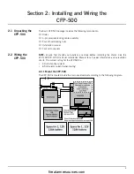
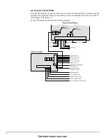
The CFP-500 is located inside the main panel cabinet according to the following diagram:
firealarmresources.com
Summary of Contents for CFP-500
Page 31: ...firealarmresources com ...


