background image

Features

2

Features

Installation

Installing the Classic PC1565

Control Panel

The following steps should be carried
out in the order described below. This
will help reduce the overall installation
time.

Before carrying out any installation
work, it is always advisable to walk the
site and check the proposed location
of all the equipment you are intending
to install.

1.

Run all cables from the location
of the detectors or modules back
to the main control panel or zone
expander units.

2.

Insert the five nylon studs through
the back of the steel cabinet and
mount the cabinet on the wall. Fit
the control panel to the wall.
Insert the PCB onto the nylon
studs until it locks into place.
Connect the two yellow leads
from the transformer into the AC–
in terminals on the PCB.

3.

Fit the remote keypad, detectors
and internal & external sounders
in the areas described on the
specification.

4.

Connect the mains cable to the
unswitched fuse spur and to the
control panel. DO NOT POWER
UP YET.

Installing the Classic PC1565 Control Panel

31

Using the Big Books

also includes a list of all additional
modules available with a brief descrip-
tion of what each module will do.

Section 2 refers to wiring the control
panel, including a description of the
main panel terminal strip, the connec-
tion and operation of the Keybus,
current ratings of modules, module
supervision and zone wiring.

Section 3 is a summary of all the user
keypad commands including arming,
disarming, auto bypass and all the
keypad commands. Also included is a
description of the operation of the
function keys and partition and global
keypads.

Section 4 is simply a description of
how to programme the panel.

Section 5 is broken down into subsec-
tions. Each contains a description of
how a particular feature works with
certain words in the description in
bold print. These bold-printed words

Summary of Contents for Classic PC1565

Page 1: ...Unit C51 Winfrith Technology Centre Winfrith Newburgh Dorchester DT2 8DH Telephone 01305 851700 Fax 01305 851660 Email Sales dscuk co uk Web Site www dscuk co uk Unit 21 Hull Business Centre Guildhall...

Page 2: ...ation 29 The Language Barrier 29 Using the Big Books 30 Using the Big Books The summary of programme options is also a good troubleshooting tool For example if you are having diffi culty getting the p...

Page 3: ...1482 322228 329911 Features 32 Using the Big Books are the options that you need to programme in order to have the features work appropriately Now look at page 27 This is the beginning of the Programm...

Page 4: ...external sounders in the areas described on the specification 4 Connect the mains cable to the unswitched fuse spur and to the control panel DO NOT POWER UP YET InstallingtheClassicPC1565ControlPanel...

Page 5: ...nications if pro grammed InstallingtheClassicPC1565ControlPanel Features 30 Features UsingtheBigBooks How to use the Installation Manual included with this panel The Installation Manual that accom pan...

Page 6: ...it 1 02 Delay 2 Final Exit 2 03 Instant Normal Zone 05 Interior Stay Away Part Set Zone will be omitted if no Final exit zone is activated Zone arms if final exit activated 06 Delay Stay Away zone Alw...

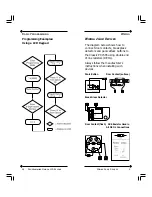
Page 7: ...565 using double end of line resistors DEOL Always follow the manufacturer s instructions when installing such devices Panic Button Door Contact surface Break Glass Detector Door Contact flush 5K6 Res...

Page 8: ...ion and set the time and date Wiring PIRs 27 Basic Programming Be sure to record your new Master Code on the System Information page in this booklet NOTE We recommend that the factory default or obvio...

Page 9: ...dash indicating the option is now OFF Go through each of the options in the section and determine if the option should be ON or OFF Once all the options are selected correctly press the key The keypa...

Page 10: ...ault setting of single end of line resistors to our recommended double end of line resistors Open the Installation Manual to page 29 30 and find section 013 First System Option Code section 013 is a t...

Page 11: ...l entries in section 005 require 3 digits To get into engineering programming mode you must press 8 followed by your engineering code At default this will be 5555 At this point the keypad will display...

Page 12: ...Clearing Troubles 1 Further Sub Menu of Troubles If 1 comes ON push 1 again for specific trouble present LED lit after pushing 1 again will indicate type of trouble 1 Low Battery Check Battery May be...

Page 13: ...ry out the following check the connections on all Keybus connected devices check the cable run distance check that cable type is 22 Clearing Troubles 4 Failure to Communicate Panel unable to send info...

Page 14: ...Features Clearing Troubles If the orange Trouble LED is lit there is trouble on the system To view press 2 The trouble condition will be dis played on the LCD keypad Scroll through the display using...

Page 15: ...Commands 8 Access to Engineering Functions Press 8 Engineer Code to enter engineering functions Installation Manual page 12 9 Arming without Entry Delay Press 9 Access Code the panel will remove the e...

Page 16: ...pad will flash the program light and turn on the zone light for any codes already programmed Enter the two digit user number for the code you want to program The corresponding zone light will flash En...

Page 17: ...by using commands These com mands are very similar on all DSC products 1 Zone Bypass Features Enter 1 Bypass light flash Enter two digit zone number to bypass Zone light ON push key 2 Display Trouble...

Page 18: ...Features 16 Features Classic PC1565 Expansion Flowchart Classic PC1565 Expansion Flowchart 17 Features...

Reviews: