Installation Instructions
LC-105DGB
Shock & Glass Breakage Detector
LC-105DGB belongs to the new generation of glass breakage detectors. The LC-105DGB can detect glass cutting by diamond in addition
t o t h e im p r o ved de t ect io n o f g las s b r eak ag e. T h is is ach ie ved b y o u r n ew all- d ig it a l si g n al p r o ces sin g
.
The LC -105D GB offers the solution for the false-alarms problem. The LC-105DGB detects the unique patterns of sound emitted by breaking or
cutting glass. The LC -105DGB does not have to be attached to the window, providing volume protection, and allows the protection of several
windows using one detector.
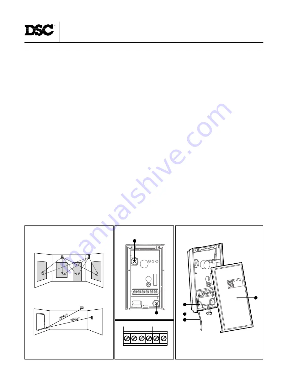
Fig. 1
- Dete ctor Mo unnting
Fig. 4
- Termina l blo ck
1
2
3
4
5
6
TAMPER
- 12V +
RELAY
A
A
Fig. 2
- Detecto r Instal latio n
TYPICAL INSTALLATION
Mounting
The detector offers flexible installation. It can be either ceiling mounted or wall mounted as shown in Fig. 1.
Selecting mounting location
If heavy blinds or curtains cover the glass, you must locate the detector behind the blinds on the window frame or above it, otherwise the blinds
might block the sound. Make sure to test the unit thoroughly using a glass break simulator for proper detection. Install the detector in a direct
line of sight with the protected glass. Do not mount the unit in front of air ducts, or close to bells (measuring 0.5m or larger in diameter). For
pr otecting s everal w indow s i n one room, locate the detec tor at opti mal distance from them to achi ev e the bes t detec tion.
Note:
for symmetrical cover of the detection area it is recommended to place the detector on the ceiling.
CONN ECTIN G THE D ETECTOR
(Fig. 2,3&4)
1.
Use a small screwdriver to release the top of the case and lift open the case (Fig. 3-1,2) There is no need to remove the PC B (Printed Circuit
Board) from the case).
2.
Insert the wires through the w iring hole (Fig. 3-3).
3.
Use the mounting holes (Fig. 2-A) to mount the detector.
4.
Connect the wires to the terminal. (Fig.4).
5.
Close the case.
JUMPERS
LED ON:
LEDS enabled
LED OFF:
LEDS disabled
Shock ON:
This is the normal working mode. Both breaking glass sound and breaking glass shock-wave
are necessary for generating an alarm.
Shock OFF:
This mode i s used only for ins tallation settings. The sound of breaking glass is enough to generate an alarm.
WIRE CONNECTIONS
Terminal Block Connections
(See fig. 4).
Terminal 1 (Marked "-").
Connect to the return Voltage or ground of the control panel.
Term in al 2 ( Marked "+") .
C onnec t to the posi tive Voltage of 9- 16 VD C sour ce (us ually fr om the alar m control unit).
Terminals 3 & 4 (Marked TAMPER ).
If a Tamper function is required connect these terminals to a 24 hours normally closed protective zone in
the c ontr ol unit. If the fr ont cover of the detector is opened, an imm edi ate alarm signal wi ll be sent to the c ontr ol unit.
Term in als 5 & 6 ( Marked R E LAY) .
T hese ar e the output relay c ontacts of the detector. Stand by - N .C / A larm - N .O
Fig. 3
- Detector Insta llation
4
2
1
3


