3
INSTALLATION
Bench Testing
The PC2585 contains a factory default program. Any additional programming required can be done through the
keypad. For many applications all that will be required is to enter the telephone number and alarm codes with keypad
entries that are as straight forward as dialing a telephone number. If you need help talk to your DSC equipment
distributor.
The following items are required for bench testing:
• 1 Single Pole Single Throw (SPST) switch,
• 1 Single Pole Double Throw Centre-off (SPDT) switch
• 2 5600
Ω
resistors.
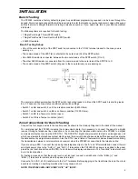
Bench Testing Set-up
• One of the outer leads (A) of the SPST switch is connected to the “COM” terminal closest to the zone you are
working on.
• The common lead of the SPST (B) is shorted to the outer lead (D) of the SPDT switch.
• One 5600
Ω
resistor is connected between the two outer leads of the SPDT switch (D to F).
• The other 5600
Ω
resistor is connected from the common lead to the outer lead of the SPDT (E to F).
• The common lead of the SPDT switch (E) goes to the zone terminal you are working on.
The normal condition exists when the SPST switch is shorting leads A to B and the SPDT switch is shorting leads
E to F. These are the zone status conditions and switch settings:
• Switch 1 on AB and switch 2 on EF is a restoral condition (5600 Ohms).
• Switch 1 on AB and switch 2 on EE is an Alarm condition (11200 Ohms).
• Switch 1 on BC is a Tamper condition (open).
• Switch 2 on DE is a Tamper condition (short).
Zone Connections for Bench Testing
Connect the four keypad wires to the control panel as shown in the Hook-up Diagram in the back of this manual.
To completely test the PC2585 including the communicator data, it is necessary to connect the panel to a digital
receiver through a telephone line connection or by connecting the telephone terminals on the PC2585 to a digital
communicator test set such as the DSC DTS-1. The DSC DTS-1 digital communicator test set is an inexpensive unit
which can simulate the telephone system dial tone and the receiver hand shake and kiss-off tones as well as display
the data sent out by a digital communicator. Also, the DTS-1 has a “listen-in” feature which makes it ideal for monitoring
the transmission between communicator and receiver when the PC2585 is connected to the telephone line.
If you are using a DTS-1, connect the red and green telephone clips to the “A” and “B” terminals and connect the red
and black power clips to the “AUX [+]” and “AUX [-]” terminals on the PC2585. When power is applied to the panel
press the red local-line button on the DTS-1 and observe the display window area. The “local-line” indicator should
be in the local position.
For testing purposes, so that the sound level is not too loud, connect a small buzzer to the “BELL [+]” and
“BELL [-]” terminals to indicate when the panel is in alarm.
Connect a 16.5 VAC, 40 VA transformer to the “AC” terminals. Before plugging in the transformer be sure the circuit
board is not resting on anything metallic which may cause a short.
NOTE: THE PC2585 WILL NOT START UP IF “AC” IS OFF.
Summary of Contents for PC2585
Page 55: ......


