background image

1

TABLE OF CONTENTS

INTRODUCTION

3

Features .................................................................................................................................................. 3

Specifications .......................................................................................................................................... 3

INSTALLATION

4

Mounting the Panel ................................................................................................................................. 4

Mounting the Keypad .............................................................................................................................. 4

Wiring ...................................................................................................................................................... 5

Burglary Zone Wiring .............................................................................................................................. 5

Auxiliary Power Connection .................................................................................................................... 5

PGM Terminal Connections .................................................................................................................... 5

STR Terminal Connection ....................................................................................................................... 5

KEY Terminal Connection ....................................................................................................................... 6

AC Power Wiring ..................................................................................................................................... 6

Battery Connection ................................................................................................................................. 6

Telephone Line Wiring ............................................................................................................................ 6

KEYPAD FUNCTIONS

7

Introduction ............................................................................................................................................. 7

Master Code ............................................................................................................................................ 7

Installer’s Programming Code ................................................................................................................ 7

Arming ..................................................................................................................................................... 7

Auto-Bypass/Stay-Away Arming ............................................................................................................. 7

At-Home Arming ...................................................................................................................................... 7

Disarming ................................................................................................................................................ 8

Important Note about Keypad [

] Commands ...................................................................................... 8

[

]+[0]:Quick-Arm .................................................................................................................................. 8

[

]+[1]+[Access Code]: Zone Bypassing ............................................................................................. 8

[

]+[2]:Display Trouble Conditions ....................................................................................................... 8

[

]+[3]:Display Alarm Memory .............................................................................................................. 9

[

]+[4]:Bell Test ..................................................................................................................................... 9

[

]+[5]+[Master Code]: Program Access Codes ................................................................................. 9

[

]+[6]:Door Chime On/Off .................................................................................................................... 9

[

]+[7]:Utility Output Command ............................................................................................................ 9

[

]+[8]+[Installer’s Code]: Installer’s Programming Command .......................................................... 10

[

]+[9]+[Access Code]: At-Home Arming ........................................................................................... 10

Keypad Zones ....................................................................................................................................... 10

Adjusting the Keypad Sounder Tone and Backlighting ....................................................................... 10

Summary of Contents for PC560

Page 1: ...CTIONS 7 Introduction 7 Master Code 7 Installer s Programming Code 7 Arming 7 Auto Bypass Stay Away Arming 7 At Home Arming 7 Disarming 8 Important Note about Keypad Commands 8 0 Quick Arm 8 1 Access...

Page 2: ...s PGM Terminal 14 05 First System Option Code 15 06 Second System Option Code 15 07 Third System Option Code 16 08 First Phone Number 16 09 Second Phone Number 16 10 Customer Account Code 16 Disabling...

Page 3: ...el Four fully programmable zones Zones are End of Line Resistor supervised All zones programmable as 24 Hour Pulsed Alarm zones Maximum zone loop resistance 100 ohms Bell Siren Output fused for 5A Bel...

Page 4: ...nted at a height convenient for all users Disassemble the keypad by pressing gently on the locking tab found on the bottom of the unit With the tab disengaged pull the backplate from the keypad Prepar...

Page 5: ...STOR LOOPS USING NC DEVICES ONLY Wire Gauge 1900 579 3000 914 4900 1493 6200 1889 7800 2377 24 22 20 19 18 Maximum wire length to End of Line Resistor feet meters Figures are based on maximum wiring r...

Page 6: ...the battery voltage drops to approximately 9 5 V or lower the battery will be automatically disconnected and the panel will power down To power up again AC power will have to be re established This f...

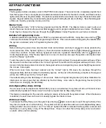
Page 7: ...when the Ready light is ON To arm the system enter a 4 digit Access Code As each digit is entered the keypad sounder will beep When the Access Code has been entered the Armed light will come ON and t...

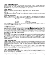
Page 8: ...open With the system disarmed enter 1 Access Code to display the bypassed zones the zone lights of bypassed zones will come ON Ensure that any zone displayed as being bypassed is intentionally bypasse...

Page 9: ...e If another code is to be changed press the number key for the code to be programmed and enter the new 4 digit code When all desired changes are complete press the Key to return to Ready Erasing a Co...

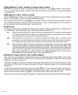
Page 10: ...eypad will sound a series of short beeps once the system has accepted the alarm P Press and hold the P Key for 2 seconds to generate a P Key alarm An alarm will be transmitted to the monitoring statio...

Page 11: ...e same number When all data for the section is completely entered the keypad sounder will beep several times to indicate that all expected data has been entered When a section is completely programmed...

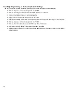
Page 12: ...ect the PGM and Zone 1 terminals together 4 Apply power to the PC560 and wait for 10 seconds 5 After approximately 10 seconds the keypad sounder will beep and Zone Light 1 will come ON 6 Remove all po...

Page 13: ...lay The zone will also have the standard Entry Delay provided that a Delay Zone has been activated before the Interior Zone If the premises are entered without coming through a Delay zone and an Inter...

Page 14: ...Access Code The default setting is 4 minutes 03 Installer s Code The default setting for the Installer s Code is 0560 It is strongly recommended that the Installer s Code be reprogrammed before instal...

Page 15: ...Handshake 3 ON DLS Answer enabled OFF DLS Answer disabled 4 ON Ringback enabled OFF Ringback disabled Factory default settings If DLS Answer is disabled the PC560 will not answer calls from a downloa...

Page 16: ...in Section 10 HEX digits may be used in the Account Code Where a zero is required in the account code enter HEX A 1 If a 3 digit code is required as in 3 1 formats enter 0 as the LAST digit The 0 rep...

Page 17: ...nd then once every 24 hours after the initial transmission If the Police Code is programmed and enabled by turning ON zone Light 4 in Section 05 it will be transmitted to the monitoring station if two...

Page 18: ..._____________ Phone ________________________ Name ________________________________ Phone ________________________ ZONE INFORMATION Zone Type Protected Area 1 ____________________ _____________________...

Page 19: ...utput Options PGM Terminal Page 14 Default 0 1 Programmable Output 01 7 Utility Output Command activates PGM 02 PGM follows Keypad Buzzer 03 Arm Disarm Status 04 Remote Operation through Downloading 0...

Page 20: ...fault Zone Light ON Zone Light OFF ON Zone Light 1 Restorals on Disarming Restorals on Timeout OFF Zone Light 2 For Future Use OFF Zone Light 3 For Future Use OFF Zone Light 4 For Future Use 08 First...

Page 21: ...Zone restorals are transmitted when the zone is restored All other restorals are transmitted on Bell Time out or on disarming depending upon the option selected in Section 07 12 Opening and Closing Re...

Page 22: ...ode allows the panel to confirm that a valid downloading computer is requesting access to the panel 15 Do Not Use Page 17 Default 0 6 0 Programming Section 15 is normally used only upon instruction fr...

Page 23: ...23 HOOK UP DIAGRAM...

Page 24: ...determined and which may be revised from time to time will be charged for each unit repaired Products which Digital Security Controls Ltd determines not to be repairable will be replaced by the neares...

Page 25: ...not properly alert occupants of a fire for a number of reasons some of which follow The smoke detectors may have been improperly installed or positioned Smoke may not be able to reach the smoke detec...

Page 26: ...1997 Digital Security Controls Ltd 1645 Flint Road Downsview Ontario Canada M3J 2J6 Printed in Canada 29000870 R3...

Page 27: ...s manual contains information on limitations regarding product use and functionandinformationonthelimitationsastoliabilityofthemanufacturer The entire manual should be carefully read Security Products...

Reviews: