background image

2

The WS4920 is a wireless repeater designed to extend the range of DSC one-way wireless 
transmitters and to improve signal quality between the transmitter and receiver. Use the WS4920 to 
remedy transmission problems caused by excessive noise or other interference, or by long distances 
between devices and receivers. The maximum recommended number of WS4920’s per alarm 
system is 4.
Each enrolled WS4920 occupies a zone slot. The WS4920 does not increase the number of 
supported wireless zones. This is determined by the control panel’s wireless receiver. Only zones 
requiring repeat functionality need to be enrolled on the WS4920. Ensure these zones are enrolled on 
both the WS4920 and the receiver/control panel.

Unpacking

Ensure your package includes the following:

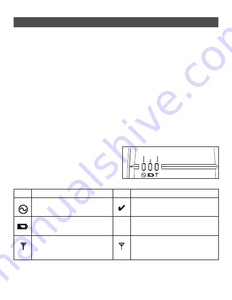
Controls and Indicators

Table 1: LED Definitions

Introduction

• One WS4920 (rechargeable Ni-MH battery included)
• One direct plug-in transformer (Not included in all configurations)
• Mounting hardware pack, including plastic wall plugs and screws
• Installation instructions

The WS4920 has three LEDs on the front. The 

meaning of these LEDs is different when in 

normal operational mode (cover on) than when 

in Installer mode (cover off). See the table 

below for descriptions of LED functionality. 

The wall tamper must be closed for the LEDs 

to operate.

Figure 1: LED Indicators

LED

Normal Mode


(cover on)

LED

Installer Mode


(cover off)

Green On: AC present

Flashing: No AC, battery good

Off: No AC and dead battery

Green 1 flash: Enrolled

Flashing: Placement test active

Red On: Battery not connected

Off: Battery good (if AC on)

Flashing: Low battery

Red Flashing: Zone not enrolled

Yellow On: RF jam present

Off: No RF jam

Yellow On: Repeater placement test “bad”

Off: Repeater placement test “good”

Flashing: Sporadic interference or valid 

transmission packets detected

Green

Yellow

Red

X

X

Summary of Contents for WS4920

Page 1: ...uipment is intended to be used WARNING READ and SAVE These Instructions Follow All WARNINGS AND INSTRUCTIONS specified within this document and or on the equipment WS4920 v1 0 Installation Instructions Instructions d installation Instrucciones de Instalación Instruções de Instalação Istruzioni di installazione ...

Page 2: ...Instruct the end user regarding the safety precautions that shall be observed when operating this equipment SAFETY precautions required during installation NEVER install this equipment during a lightning storm NEVER touch uninsulated wires or terminals unless the direct plug in transformer has been dis connected Ensure that cables are positioned so that accidents cannot occur Connected cables must...

Page 3: ...0 433 PC4010 433 SCW9055 57 D G I 433 ULRF5132 433 UL RFK5500 433 UL RFK5501 433 UL RFK5508 433 UL RFK5516 433 UL RF4164 433 PC5132 433 RF5108 433 RF5501 433 Motion Detector Wireless Key Smoke Detector UL WLS914 433 ULWS4904 P WS4904M UL WS4939 WS4949 WS4959 WS4969 WS4979 UL WS4916 ULWS4926 Glassbreak Detector CO Detector Hold Up Alarm ULWLS912L 433 WS4913 WLS928 433 Shock Sensor Flood Sensor Pani...

Page 4: ...to the local authorities Secondary 16VAC 18VAC 20VA The following plug in transformers shall be used USA PTD1620U UL CC5 efficiency level IV 16 5V 20VA UL listed installations Canada PTD1620N C UL certified 16 5V 20VA ULC listed installations Europe PTD1620T EU CE approved 230V 16 5V 20VA Maximum allowed wire run distances Only UL listed devices can be used in UL Commercial Burg listed installatio...

Page 5: ...tions Introduction One WS4920 rechargeable Ni MH battery included One direct plug in transformer Not included in all configurations Mounting hardware pack including plastic wall plugs and screws Installation instructions The WS4920 has three LEDs on the front The meaning of these LEDs is different when in normal operational mode cover on than when in Installer mode cover off See the table below fo...

Page 6: ...rking method If the selected location fails the placement test the device must be repositioned Step 2 Connecting Power Connect back up battery first then AC To connect the battery 1 Gently open front cover using small slotted screwdriver in holes provided see Figure 3 The WS4920 includes a Programming button used to place it into Enroll Placement modes A 4 position DIP switch is also provided to s...

Page 7: ...ake several hours to clear To connect the AC adaptor 1 Run AC wire through channel on back of WS4920 and pass through hole in enclosure 2 Connect AC wires to terminals on PC board see Figure 4 3 Route wire around retaining bracket to secure 4 Plug AC adaptor into wall outlet Figure 3 Removing the Cover Figure 4 Power Connections Figure 5 Wire Routing AC Terminals Battery Connector ...

Page 8: ...ation manual NOTE For PowerSeries Alexor MAXSYS and SCW9045 47 use the serial number beginning with 2 For the Impassa SCW9055 SCW9057 use the serial number beginning with A NOTE For non UL listed installations Non alarm zone type 26 is recommended With this zone type loss of AC or a low battery condition are not reported to the central station The alarm panel does not show a trouble for the zone b...

Page 9: ...y be enrolled with one WS4920 The only exception is in UL ULC Residential Fire installations where smoke and CO detectors that are enrolled with a WS4920 must be enrolled with at least two WS4920 s Fobs and panic pendants may be enrolled with multiple WS4920 s If an enrollment is attempted after all 164 device slots have been filled the WS4920 emits a 2 second error tone and all three LEDs light f...

Page 10: ...ough mounting holes using all 4 wall plugs and screws provided 3 Place cover back on WS4920 4 Plug AC adaptor into unswitched AC outlet Restoring the WS4920 to Factory Defaults To restore factory default settings 1 Within 1 minute of power up press and hold Programming button for 10 seconds Sounder beeps after first second to indicate WS4920 is in Installer mode After 10 seconds WS4920 emits doubl...

Reviews: