background image

Section 4: Programming Options

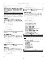
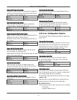
Device Label

This section is used to program a custom label for the

device.

Default:

Zone ZZZ

Valid range:

32 character ASCII

Zone Attribute

This section is used to customize zone behavior for the

device. The table below specifies the status of each attribute

for this device.

See on page 43 for attribute definitions.

Door Chime

Enabled

Alarm Report

Enabled

Burglary Verified

Enabled

Transmission Delay

Enabled

Bell Audible

Enabled (read-only)

Bell Steady

Enabled (read-only)

Bypass Enable

Enabled (read-only)

Force Arm

Disabled (read-only)

Swinger Shutdown

Enabled (read-only)

Two Way Audio

Enabled (read-only)

Talk Listen

Enabled (read-only)

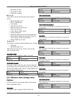
Supervision

This section is used to enable/disable wireless supervision

of the device. Supervision monitors the presence of the wire-

less device on the alarm system.

Default:

Enabled

Valid range:

Enabled/Disabled

4.6.7 Wireless Temperature Con-
figuration Options

The following sections are used for programming wireless

temperature sensors.

Note:

Wireless temperature feature was not evaluated by

UL/ULC.

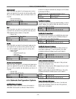
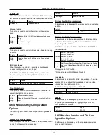
Device Enable/Disable

This option is used to enable and disable the wireless

device.

Default:

Enabled

Valid range:

Enabled/Disabled

Device Partition Assignment

This option is used to enable and disable the wireless

device.

Default:

Enabled

Valid range:

1

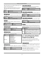
Chime Tone

This option is used to select the tone emitted by the device

when the zone is tripped.

Default:

Disabled

Valid range:

Beeps, Bing Bing, Ding Dong, Alarm Tone

Zone Type

This option is used to program a zone type for the device.

Default:

24-hour Temperature

Valid range:

24-hour Temperature

Device Label

This option is used to program a custom label for the wire-

less device.

Default:

Zone ZZZ

Valid range:

32 character ASCII

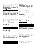
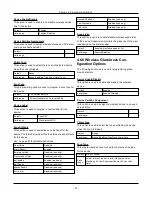
Zone Attribute

This section is used to customize zone behavior for the

device. The table below specifies the status of each attribute

for this device.

See on page 43 for attribute definitions.

Door Chime

Disabled

Alarm Report

Enabled

Burglary Verified

Disabled

Transmission Delay

Enabled

Bell Audible

Enabled (read-only)

Bell Steady

Enabled (read-only)

Bypass Enable

Enabled (read-only)

Force Arm

Disabled (read-only)

Swinger Shutdown

Disabled (read-only)

Two Way Audio

Disabled (read-only)

Talk Listen

Disabled (read-only)

Supervision

This option is used to enable/disable wireless supervision of

the device. Supervision monitors the presence of the wire-

less device on the alarm system.

- 35 -

Summary of Contents for WS900-19UL

Page 1: ...Reference Manual Models WS900UL WS901 WARNING This manual contains information on limitations regarding product use and function and information on the limitations as to liability of the manufacturer...

Page 2: ...3 1 3 WPS Mode 8 14 3 2 Arming and Disarming Methods 14 3 2 1 Away Arming 14 3 2 2 Stay Arming 14 3 2 3 Quick Arming 15 3 2 4 Disarming 15 Section 4 Programming Options 16 4 1 Integrated Keypad Optio...

Page 3: ...Available Zone Types 42 4 8 Available Zone Attributes 43 4 9 Diagnostics Read Only 43 4 10 System Control 43 4 10 1 Device 44 4 10 2 Network 44 Section 5 Troubleshooting 45 5 1 Testing 45 5 2 Viewing...

Page 4: ...asures to minimize the risks to that person or other persons This equipment has no mains on off switch if the equipment must be quickly disconnected the plug of the direct plug in power supply is inte...

Page 5: ...00 supports two way audio Model Differences The table below lists the features of each alarm system model Model PowerG MHz Wi Fi GHz Z Wave MHz 2 Way Audio WS900 19UL 915 2 4 No Yes WS900 29UL 915 2 4...

Page 6: ...dual tech motion detector PGx984 P Wireless mirror motion detector PGx974 P UL Wireless outdoor motion detector PGx994UL Wireless glass break detector PGx912 PGx922UL Wireless shock detector PGx935UL...

Page 7: ...ontrol panel Central Monitoring Station Receivers Receiver Sur Gard System I IP Receiver SG System I IP Receiver Sur Gard System II Receiver SG System II Receiver Sur Gard System III Receiver SG Syste...

Page 8: ...ning devices supported models PGx901 indoor PGx911 outdoor l Programmable as steady pulsed temporal three as per ISO8201 or temporal four CO alarm l Warning device sounds alarms in the following prior...

Page 9: ...1 EN50136 2 1 EN50136 2 3 ATS 2 l Compliant with EN50136 1 1 EN50136 2 1 ATS2 requirements System Supervision Features The iotega continuously monitors a number of possible trouble conditions and pro...

Page 10: ...plug in adapter to the power connector on the back of the panel Route the power cable through the strain relief channel on the bottom of the panel then plug the adapter into an AC outlet The iotega po...

Page 11: ...wer cable Strain Relief 2 Access Cover for Battery SIM Card and Reset Button 3 Speaker 4 Battery 5 Reset button 6 SIM card 7 Tamper switch Removing the Battery 1 Remove the access cover from the back...

Page 12: ...the retention tab clicks into place 4 Replace the back cover of the panel 2 2 Controls and Indicators The iotega provides a series of LED indicators to notify users of system status Figure 2 5 LED Ind...

Page 13: ...Armed ON Steady Red Partition is armed Flashing Red System in Alarm Note this LED does not flash for silent alarms or panic alarms Flashing Amber System Test AC Ready Trouble Arm LED s WiFi Trouble C...

Page 14: ...rver is active ON Flash Red Link to remote server is active but has failed to communicate OFF Link to remote server is not active Flashing Amber System Test AC Ready Trouble Arm LED s WiFi Trouble Cel...

Page 15: ...above process until all devices are enrolled The wireless devices in the table below each have a dedicated Enroll button located on the circuit board inside the plastic casing A Phillips screw must be...

Page 16: ...ries return to previous screen 2 for Troubles see on page 45 8 to enable WiFi access point for adding IP devices such as the touchscreen keypad See on the facing page Shift mode switches between numer...

Page 17: ...ators turn on and If the Audible Exit Delay option is enabled the keypad beeps once every second during the exit delay and three times a second during the last 10 seconds to alert the user to leave vi...

Page 18: ...29 3 2 4 Disarming The user must enter through a door programmed as Delay Upon entering the panel emits a steady entry delay tone and a pulsing tone during the last 10 seconds of entry delay to alert...

Page 19: ...nitoring station Default Enabled Valid range Enabled Disabled Auxiliary Button Options This function is used to enable or disable the Auxiliary A button on the integrated keypad When enabled pressing...

Page 20: ...t SIA Valid range SIA CID Bell Squawk on Arming With this option enabled the iotega chirps the sirens briefly at full volume when the system is successfully armed The following options are provided to...

Page 21: ...g When this option is enabled an access code is required to view the zone bypass menu When this option is disabled the zone bypass menu is accessible to anyone Default Disabled Valid range Enabled Dis...

Page 22: ...rvisory window up to a maximum time of 18 hours After 18 hours fire detection devices go into fault regardless of the programmed supervisory window Default Disabled Valid range Enabled Disabled Wirele...

Page 23: ...ays Valid range 000 to 255 days A Key Alarm control for 2 way Voice When this option is enabled a 2 way talk listen in session is initiated when the Auxiliary A key is tapped Default Enabled Valid ran...

Page 24: ...d to the central monitoring station when they occur When disabled maintenance events are not reported l Event Buffer Full l Close Delinquency l Cold Start l Installer Lead In Out l FW Update Begin Suc...

Page 25: ...on is obtained When DHCP is selected the iotega is automatically assigned an IP address by the network When Static IP is selected a consistent IP address is used Default DHCP Automatic Valid range DHC...

Page 26: ...d for cellular data connectivity Default Blank Valid range 32 ASCII characters or Null Panel s Cellular Login User Name This section is used to program a user name for cellular net work connection Def...

Page 27: ...nd port number with identical values Note When operating in common receiver mode Ethernet Receiver 1 account code is used for Ethernet and Cellular Default 127 000 000 001 Valid range 000 000 000 000...

Page 28: ...thernet Receiver 1 and Ethernet Receiver 2 local ports with the same value Default 0000 to 65535 Valid range 0000000000 to FFFFFFFFFF CMS Ethernet 2 Remote Port This section is used to program the por...

Page 29: ...t not used CMS Cellular 2 IP Address Enter the Cellular receiver 2 IP address This IP address will be provided by the central monitoring station Note When a valid address has been entered Cellular Rec...

Page 30: ...ellular is used test transmission shall be 24 hours for ULC and 7 days for UL Valid range 000 to 255 Days Commercial Supervision When this option is enabled swap detection is provided on the superviso...

Page 31: ...ed Valid range Enabled Disabled Microphone Gain This section is used to program the volume level of the built in microphone 001 is the lowest volume level 000 disables the microphone Default 001 Valid...

Page 32: ...e the automatic bypass on Stay Away zones remains Note Quick Exit cannot be initiated from the integrated keypad Default Disabled Valid range Enabled Disabled Internal Siren When this option is enable...

Page 33: ...signment This section is used to program the partition that the wirefree keypad is assigned to Default 1 0 to 255 1 2 Both Fire Button Options When this option is enabled pressing and holding the Fire...

Page 34: ...d Valid range Read only Local Clock Display Option When this option is enabled the keypad displays the time and date when not in use Default Enabled Valid range Read only Keypad Lockout Duration This...

Page 35: ...the user is locked out of the system Default Disabled Valid range Enabled Disabled 4 6 3 Wireless Siren Configuration Options The following section provides descriptions of all wireless siren programm...

Page 36: ...option is enabled the alarm panel receives com mands from the enrolled wireless key Default Enabled Valid range Enabled Disabled Wireless Key Partition Assignment This option is used to assign the wir...

Page 37: ...ay Disabled read only Bell Audible Enabled read only Bell Steady Disabled read only Bypass Enable Disabled read only Force Arm Disabled read only Swinger Shutdown Disabled read only Two Way Audio Disa...

Page 38: ...nable and disable the wireless device Default Enabled Valid range Enabled Disabled Device Partition Assignment This option is used to enable and disable the wireless device Default Enabled Valid range...

Page 39: ...Low Temperature alarm This option is disabled by entering 999 or 999 Default 999 Valid range 999 to 999 4 6 8 Wireless Flood Configurations The following sections are used for programming wireless fl...

Page 40: ...r Follower Valid range Instant Interior Follower Interior Stay Away Delay Stay Away 24 Hour Supervisory Buzzer 24 Hour Non Alarm Zone Attribute This section is used to customize zone behavior for the...

Page 41: ...is 160 x 128 dpi Default Enabled Valid range Enabled Disabled Normal Quality When this option is enabled the camera captures lower res olution images 160 x 128 dpi Default Disabled Valid range Enabled...

Page 42: ...ng a reporting timer When motion is detected the device transmits an alarm to the receiver and does not report any further events until the timer expires Any motion detected during the configured peri...

Page 43: ...ilt in reed switch The reed switch is used in conjunction with the separately mounted magnet as part of the trigger mech anism If the reed switch is enabled and a device is hardwired to the external i...

Page 44: ...d switch is enabled and a device is hardwired to the external input terminals both sensors transmit simultaniously However the iotega treats both devices as the same zone Disable the reed switch to ha...

Page 45: ...ins The alarm is triggered if the zone is still faul ted after 30 seconds If the zone is no longer in alarm an 80 second verification timer begins If any fire zone is activated during this period the...

Page 46: ...enabled the panel is able to ini tiate a 2 way audio session When not enabled only the panel microphone turns on initiating a listen in only session The speaker remains off Talk Listen 4 9 Diagnostics...

Page 47: ...he enrolled device received over a 24 hour period Now The iotega displays RF test results from the last place ment test Note For vanishing door contacts and wireless keys the device must be triggered...

Page 48: ...display the second level troubles 6 The keypad will display a second level of detail for the trouble code selected in step 5 by illuminating numbers on the keypad Refer to the table below for the mea...

Page 49: ...16 04 Fault Supervision 1 16 05 Not Networked 1 16 04 Keypad 01 AC 1 9 02 Battery Trouble 1 9 03 Tamper 1 9 04 Fault Supervision 1 9 05 Not Networked 1 9 05 Repeater 01 AC 1 8 02 Battery Trouble 1 8...

Page 50: ...ce connected to the portal a static IP can be assigned and the iotega taken to the site Network setup details for the installation site are needed to assign a valid IP 7 Static IP on unit No DHCP Eth...

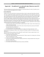
Page 51: ...t air movement the presence of joists uninsulated ceilings etc Consult National Fire Alarm Code NFPA 72 CAN ULC S553 02 or other appropriate national standards for installation recommendations l Do no...

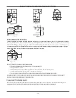
Page 52: ...sted locations in the home GROUND FLOOR BASEMENT KITCHEN GARAGE BEDROOM BEDROOM BEDROOM CARBON MONOXIDE DETECTOR Figure 5 Do NOT place the CO alarm in the following areas l Where the temperature may d...

Page 53: ...isms operate smoothly l If opening or using the exit is too difficult for children the elderly or handicapped plans for rescue should be developed This includes making sure that those who are to perfo...

Page 54: ...tact ID SIA Zone Alarm Restore Event Codes on page 56 for details Zone Restores A R Zone tamper restore MA R E 3 83 ZZZ R 3 83 ZZZ TA ZZZ TR ZZZZ Zone fault restore MA R E 3 8A ZZZ R 3 8A ZZZ UT ZZZZ...

Page 55: ...Disarmed by user O C E 4 A1 UUU OP UUUU Automatic Arming Canceled O C E 4 64 UUU CI 0000 Special Opening System disarmed using keyswitch main tenance code DLS software wireless key O C E 4 AA 000 OP 0...

Page 56: ...04 R 3 5A 004 YS 0004 YK 0004 Alternate Communicator SMS Config trouble restore MA R E 3 AA 001 R 3 AA 001 YX 0001 YZ 0001 Remote Programming Begin End MA R E 6 27 000 E 6 28 000 LB 0000 LS 0000 FTC t...

Page 57: ...less keypad 1 8 trouble restore E 3 8A 601 608 R 3 8A 601 608 UT 601 608 UJ 601 608 Wireless keypad supervisory trouble restore E 3 8A 601 608 R 3 8A 601 608 UT 601 608 UJ 601 608 Wireless keypad 1 8...

Page 58: ...restore A R E 1 AA 0000 R 1 AA 0000 MA 0000 MH 0000 Panic alarm by interactive alarm restore A R E 1 2A 0000 R 1 2A 0000 PA 0000 PH 0000 Miscellaneous Closing Zone Bypass at time of arming O C E 5 7A...

Page 59: ...ZZZ R 1 3A ZZZ Interior BA ZZZZ BH ZZZZ E 1 3A ZZZ R 1 3A ZZZ Interior Stay Away BA ZZZZ BH ZZZZ E 1 3A ZZZ R 1 3A ZZZ Delay Stay Away BA ZZZZ BH ZZZZ E 1 3A ZZZ R 1 3A ZZZ Day Zone BA ZZZZ BH ZZZZ E...

Page 60: ...taller portal Panel Settings Panel Configuration Partition Configuration Entry Delay 1 l The exit delay shall not exceed 120 seconds refer to Installer portal Panel Settings Panel Configuration Partit...

Page 61: ...thods etc to casual users baby sitters or service people User Information The installer should advise the users and note in the User s Manual l Service organization name and telephone number l The pro...

Page 62: ...s with FCC and ISED Canada radiation exposure limits set forth for an uncontrolled environment The antenna should be installed and operated with minimum distance of 20 m between the radiator and your...

Page 63: ...ange 45 120 sec Default 60 sec Required programmable Exit Time Restart hardcoded ON Enables the exit delay restart feature Default Enabled Required Auto Stay Arm on Un vacated Premises Zones must be p...

Page 64: ...Range 001 255 seconds Default 0 seconds Allowed Swinger Shutdown for Alarms Panel Settings Zones Swinger Shutdown Access to the swinger shutdown limit for zone alarms For all non fire zones shut down...

Page 65: ...ovided the recipient agrees to the terms of this EULA If the SOFTWARE PRODUCT is an upgrade any transfer must also include all prior versions of the SOFTWARE PRODUCT Termination Without prejudice to a...

Page 66: ...ranty claim Access cards or tags returned for replacement under warranty will be credited or replaced at DSC s option Products not covered by this warranty or otherwise out of warranty due to age mis...

Page 67: ...ween intruders and intended occupants Motion detectors do not provide volumetric area protection They have multiple beams of detec tion and motion can only be detected in unobstructed areas covered by...

Page 68: ...MHz 10mW 2400MHz 2483 5MHz 100mW EGSM EDGE 880MHz 915MHz Class 4 2W 900 MHz E GSM Class E2 0 5W 900 MHz EDGE DCS EDGE 1710MHz 1785MHz Class 1 1W 1800 MHz DCS Class E2 0 4W 1800 MHz EDGE FDD Band VIII...

Page 69: ...ormation will be retained as long as necessary to achieve the purpose for which it was collected and for any period thereafter as legally required or permitted by applicable law The trademarks logos a...

Reviews: