Section 4: Programming Options
Alarm Control Panel Placement Test
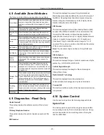
This test is used to check the panel location for signal noise
that could interfere with the proper operation of the alarm
system. If the location is good, “No noise” is displayed. If the
location has signal noise beyond system tolerance, “noise”
is displayed.
4.10.1 Device
Walk Test
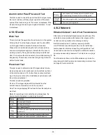
This mode tests the operation of each detector in the system.
While in Walk Test, the Ready, Armed, and Trouble LED's
on the keypad flash to indicate that the test is active.
When a zone is violated during the test, a 2-second tone
sounds on all system keypads to indicate that the zone is
working correctly. The system automatically ends the test
after 15 minutes without zone activity. An audible warning (5
beeps every 10 seconds) is sounded, beginning 5 minutes
before the test ends.
Placement Test
This test is used to determine the RF signal status for wire-
less devices and can be performed on the installer portal or
at the individual device. For instructions on placement test-
ing at the device, refer to the installation sheet included with
the wireless equipment.
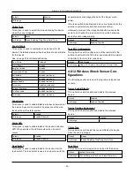
Two test results are provided:
24 Hour: The iotega displays RF test results from the
enrolled device received over a 24 hour period.
Now: The iotega displays RF test results from the last place-
ment test.
Note:
For vanishing door contacts and wireless keys, the
device must be triggered in order to get a result.
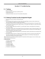
Status
Definition
Strong
Strong signal strength
Good
Good signal strength
Poor
Poor signal strength
1-Way
The alarm panel can see the device but cannot configure
or control it.
2-Way
The alarm panel can configure and control the device.
0-Way
The alarm panel cannot see or control the device.
Missing
The device has not received any communications from
the panel during the supervision monitoring period.
Not Net-
worked
The device is registered but not activated on the network.
NA
The device is not registered.
4.10.2 Network
Ethernet/Cellular 1 and 2 Test Transmission
Ethernet and Cellular test transmissions check to see if the
selected communication path between the iotega and the
central monitoring station is functioning correctly.
Both Ethernet/Cellular 1 (primary receiver) and Eth-
ernet/Cellular 2 (secondary receiver) can be tested sep-
arately based on individual reporting configurations. Test
transmissions can also be configured to alternate between
primary and secondary receivers. For details, see on page
26.
Test transmission time and test transmission cycle can be
programmed for both primary and secondary receivers. See
on page 23 for more details.
- 44 -

