background image

Operation 


057-230   ISSUE: 1 

Page 72 of 100 


5.6  MAINTENANCE ALARM  

 
Depending upon module configuration one or more levels of engine maintenance alarm may occur 
based upon a configurable schedule. 
 
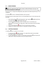
Example 1 


Screen capture from DSE Configuration 
Suite Software showing the configuration 
of the 

Maintenance Alarm

 for Oil, Air and 

Fuel. 
 
When activated, the maintenance alarm 
can be either a 

Warning

 (set continues to 

run) or

 Shutdown

 (running the set is not 

possible). 
 
Resetting the 

Maintenance Alarm

 is 

normally actioned by the site service 
engineer after performing the required 
maintenance.  
The method of reset is either by: 
 

  Activating an input that has been 

configured to 

Maintenance Reset 

Alarm 

x, where x is the type of 

maintenance alarm (Air, Fuel or Oil). 
 

  Pressing the maintenance reset 

button in the DSE Configuration Suite, Maintenance section. 


  Pressing and holding the 

Stop/Reset Mode


 button for 10 seconds on the desired Maintenance 

Alarm status page. This can be protected by a PIN number. 

 
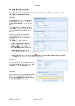
Example 2  


Screen capture from DSE Configuration Suite 
Software showing the configuration of a digital 
input for Maintenance Reset Alarm Air. 


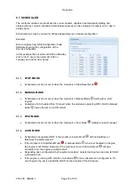
Example 3  


Screen capture from DSE Configuration Suite 
Software showing the Maintenance Alarm 
Reset ‘button’ in the DSE Configuration Suite 
SCADA | MAINTENANCE section.  


Summary of Contents for DSE6010 MKII

Page 1: ...057 230 IS 057 230 ISSUE 1 DEEP SEA ELECTRONICS PLC DSE6010 MKII DSE6020 MKII Operator Manual Document Number 057 230 Author Mark Graham...

Page 2: ...K registered trademarks of Deep Sea Electronics PLC Any reference to trademarked product names used within this publication is owned by their respective companies Deep Sea Electronics Plc reserves the...

Page 3: ...MPERATURE 14 2 8 2 3 FUEL LEVEL SENSOR 15 2 8 2 4 FLEXIBLE SENSOR 15 2 8 2 4 1 RESISTIVE CONFIGURATION 15 2 8 2 4 2 0 10V INPUT CONFIGURATION 15 2 8 2 4 3 4 20 MA INPUT CONFIGURATION 15 2 8 3 CHARGE F...

Page 4: ...48 4 4 4 FRONT PANEL EDITOR FPE AUTO RUN ICON 48 4 4 5 MODE ICON 48 4 4 6 ALARM ICONS PROTECTIONS 49 4 4 6 1 WARNING ALARM ICONS 50 4 4 6 2 ELECTRICAL TRIP ALARM ICONS 51 4 4 6 3 SHUTDOWN ALARM ICONS...

Page 5: ...TION SETTINGS 85 6 3 SELECTABLE PARAMETER SETTINGS 87 6 3 1 INPUT SOURCES 87 6 3 2 OUTPUT SOURCES 88 6 3 3 ALARM ACTION 90 6 3 4 FLEXIBLE SENSOR ALARM ACTION 90 6 3 5 POWER UP MODE 90 6 3 6 SENSOR TYP...

Page 6: ...057 230 ISSUE 1 Page 6 of 100 11 1 WEEE WASTE ELECTRICAL AND ELECTRONIC EQUIPMENT 98...

Page 7: ...the system operating parameters via the LCD display The DSE60xx MKII module monitors the engine indicating the operational status and fault conditions automatically shutting down the engine and givin...

Page 8: ...ng CTs With DSE Products 056 010 Over Current Protection 056 022 Breaker Control 056 029 Smoke Limiting 056 030 Module PIN Codes 1 1 3 MANUALS Product manuals are can be downloaded from the DSE websit...

Page 9: ...uits 35 volts or less must be supplied from the engine starting battery or an isolated secondary circuit The communication sensor and or battery derived circuit conductors shall be separated and secur...

Page 10: ...QUIREMENTS Minimum Supply Voltage 8 V continuous Cranking Dropouts Able to survive 0 V for 100 ms providing the supply was at least 10 V before the dropout and recovers to 5 V afterwards Maximum Suppl...

Page 11: ...on Common Mode Offset From Earth 100 V AC max Resolution 1 V AC phase to neutral 2 V AC phase to phase Accuracy 1 of full scale phase to neutral 2 of full scale phase to phase Minimum Frequency 3 5 Hz...

Page 12: ...e to find the VA burden of the cable itself If the CTs are fitted within the alternator top box the star point common of the CTs should be connected to system ground earth as close as possible to the...

Page 13: ...orrect connection of the phases as described above results in incorrect power factor pf measurements which in turn results in incorrect kW measurements One way to check for this is to make use of a si...

Page 14: ...cross sensor with a fixed current applied Arrangement Differential resistance measurement input Measurement Current 11 mA 10 Full Scale 240 Over Range Fail 270 Resolution 0 1 Bar 1 2 PSI Accuracy 2 of...

Page 15: ...e Fail 540 Resolution 1 Accuracy 2 of full scale resistance 9 6 excluding transducer error Max Common Mode Voltage 2 V Display Range 0 to 250 0 C to 250 C 32 F to 482 F or 0 bar to 17 2 bar 0 PSI to 2...

Page 16: ...output Whenever the generator is required to run the terminal provides excitation current to the charge alternator field winding When the charge alternator is correctly charging the battery the volta...

Page 17: ...6 25 RPM Accuracy 25 RPM Flywheel Teeth 10 to 500 Magnetic Pickup devices can often be shared between two or more devices For example one device can often supply the signal to both the DSE module and...

Page 18: ...E For further details on connection to electronic engines refer to DSE Publication 057 004 Electronic Engines And DSE Wiring Modules are fitted with the CAN interface as standard and are capable of re...

Page 19: ...module starting or stopping the generator selecting operating modes etc Additionally the various operating parameters such as output volts oil pressure etc of the remote generator are available to be...

Page 20: ...arallel with each other Either signal mutes both the internal sounder and audible alarm output Example of configuration to achieve external sounder with external alarm mute button 2 12 ACCUMULATED INS...

Page 21: ...ification Page 21 of 100 057 230 ISSUE 1 2 13 DIMENSIONS AND MOUNTING 2 13 1 DIMENSIONS 216 mm x 158 mm x 43 mm 8 5 x 6 2 x 1 5 2 13 2 PANEL CUTOUT 184 mm x 137 mm 7 2 x 5 3 2 13 3 WEIGHT 0 45 kg 1 00...

Page 22: ...is protruding from the clip Insert the three prongs of the fixing clip into the slots in the side of the module case Pull the fixing clip backwards towards the back of the module ensuring all three pr...

Page 23: ...enance Spares Repair and Servicing elsewhere in this document The optional silicon gasket provides improved sealing between module and the panel fascia The gasket is fitted to the module before instal...

Page 24: ...installed into the control panel with the optional sealing gasket 2 Front of module when installed into the control panel WITHOUT being sealed to the panel IEEE C37 2 Standard Electrical Power System...

Page 25: ...ter Or DC Generator Relay 54 Turning Gear Engaging Device 59AC AC Overvoltage Relay 59DC DC Overvoltage Relay 62 Time Delay Stopping Or Opening Relay 63 Pressure Switch 71 Level Switch 74 Alarm Relay...

Page 26: ...when the equipment enclosure is tilted at an angle up to 15 from its normal position drops falling at an angle 3 Protected against ingress of solid objects with a diameter of more than 2 5 mm Tools wi...

Page 27: ...ling dirt 2 IP31 Provides a degree of protection against limited amounts of falling water and dirt 3 IP64 Provides a degree of protection against windblown dust rain and sleet undamaged by the formati...

Page 28: ...cument 3 1 TERMINAL DESCRIPTION NOTE Availability of some terminals depends upon module version Full details are given in the section entitled Terminal Description elsewhere in this manual To aid user...

Page 29: ...mm AWG 13 Plant Supply Positive Also supplies DC Outputs A B Recommended Maximum Fuse 20A 4 DC Output A FUEL 2 5 mm AWG 13 Plant Supply Positive from terminal 2 10A for 10secs 5A resistive continuous...

Page 30: ...able specified for use with CAN must be used for the CAN link DSE stock and supply Belden cable 9841 which is a high quality 120 impedance cable suitable for CAN use DSE part number 016 030 NOTE For f...

Page 31: ...Mains L2 S output AC Recommend 2A fuse 31 Mains L3 T Voltage Monitoring 1 0 mm AWG 18 Connect to Mains L3 T output AC Recommend 2A fuse 32 Mains Neutral N Input 1 0 mm AWG 18 Connect to Mains Neutral...

Page 32: ...D POLARITY OF CT PRIMARY 3 1 5 CONFIGURABLE DIGITAL INPUTS NOTE For further details of module configuration refer to DSE Publication 057 223 DSE6010 MKII 6020 MKII Configuration Software Manual Pin No...

Page 33: ...ipment is outside the scope of Deep Sea Electronics PLC CAUTION Care must be taken not to overload the PCs USB system by connecting more than the recommended number of USB devices to the PC For furthe...

Page 34: ...rers and panel builders may use these diagrams as a starting point however you are referred to the completed system diagram provided by your system manufacturer for complete wiring detail Further wiri...

Page 35: ...Installation Page 35 of 100 057 230 ISSUE 1 3 2 1 DSE6010 MKII TYPICAL WIRING DIAGRAM 3 PHASE 4 WIRE...

Page 36: ...Installation 057 230 ISSUE 1 Page 36 of 100 3 2 2 DSE6020 MKII TYPICAL WIRING DIAGRAM 3 PHASE 4 WIRE...

Page 37: ...Installation Page 37 of 100 057 230 ISSUE 1 3 3 ALTERNATE TOPOLOGY WIRING DIAGRAMS 3 3 1 GENERATOR...

Page 38: ...Installation 057 230 ISSUE 1 Page 38 of 100 3 3 2 MAINS 6020 MKII ONLY...

Page 39: ...g points must be followed Follow the typical wiring diagram as normal for all sections EXCEPT the earth points All points shown as Earth on the typical wiring diagram should connect to BATTERY NEGATIV...

Page 40: ...e supplies NOTE The following descriptions detail the sequences followed by a module containing the standard factory configuration Always refer to your configuration source for the exact sequences and...

Page 41: ...play Stop Reset Mode Manual Mode Auto Mode Alarm Mute Lamp Test Start Fault LED Will be constant on warning and flash upon Electrical Trip and Shutdown Fault Close Generator Manual Mode Only Open Gene...

Page 42: ...Mode Test Mode Auto Mode Alarm Mute Lamp Test Start Fault LED Will be constant on warning and flash upon Electrical Trip and Shutdown Fault Transfer to Generator Manual Mode Only Transfer to Mains Man...

Page 43: ...o place the generator off load use the Transfer to Mains or Open Generator buttons The module automatically instructs the changeover device to place the generator off load Close Generator and Delayed...

Page 44: ...and cooling timer as necessary Close Generator and Delayed Load Output 1 2 3 4 become inactive at once if used The module then waits for the next start event For further details please see section ent...

Page 45: ...this manual Transfer To Generator This button is only active in the Manual Mode and allows the operator to transfer the load to the generator Open Generator DSE6010 MKII Only This button is only activ...

Page 46: ...led For further details of module configuration refer to DSE Publication 057 223 DSE60xx MKII Configuration Software Manual Inst Icon Instrumentation Unit Alarm Icon Active Config Instrumentation Unit...

Page 47: ...nstrumentation screen Mains voltage and frequency instrumentation screen DSE6020 MKII only Generator current instrumentation screen Mains current instrumentation screen DSE6020 MKII only when CT in lo...

Page 48: ...rt input is active Appears when a low battery run is active Mains failure Appears when a scheduled run is active 4 4 5 MODE ICON An icon is displayed in the Mode Icon section to indicate the mode the...

Page 49: ...cal trip or shutdown alarm the module displays the Alarm Icon and the Stop Reset Mode button LED begins to flash If multiple alarms are active at the same time the Alarm Icon automatically cycles thro...

Page 50: ...s below the low fuel level pre set pre alarm setting High Fuel Level The level detected by the fuel level sensor is above the high fuel level pre set pre alarm setting Battery Under Voltage The DC sup...

Page 51: ...load before shutting down the engine The alarm must be accepted and cleared and the fault removed to reset the module Electrical trips are latching alarms and to remove the fault press the Stop Reset...

Page 52: ...cts that an input configured to create a fault condition has become active Fail To Start The engine has failed to start after the configured number of start attempts Low Oil Pressure The module detect...

Page 53: ...U has detected an alarm CHECK ENGINE LIGHT Contact Engine Manufacturer for support CAN Data Fail The module is configured for CAN operation and does not detect data on the engine Can data link Emergen...

Page 54: ...e desired icon is at the top press the Auto Mode button to enter that instrunmentation section If the Auto Mode button is not pressed the display automatically returns to the Home page after the confi...

Page 55: ...ss Mains And so on until the last page is reached A Further press of the navigation down button returns the display to the Home page Once selected the page remains on the LCD display until the user se...

Page 56: ...oltage reading of the generator and mains that is measured from the module s voltage inputs 230 V L1N 230 V 230 V L2N 230 V 230 V L3N 230 V Generator Voltage ph N ph ph Mains Voltage ph N ph ph DSE602...

Page 57: ...e ph ph Mains Frequency 4 5 6 LOAD These pages contain electrical values of the load measured or derived from the module s voltage and current inputs The power values displayed depend on which supply...

Page 58: ...ture Engine Oil Pressure Engine Fuel Level Flexible Sensor Engine Maintenance Due Oil Engine Maintenance Due Air Engine Maintenance Due Fuel 4 5 8 INFO These pages contain information about the contro...

Page 59: ...h up and down buttons simultaneously the navigation menu is then displayed Once entered cycle to the DTC section and enter To view the active DTC s alarms repeatedly press the up or down buttons until...

Page 60: ...at the engine speed has fallen below its configured under speed alarm level Over Speed The engine ECU has detected that the engine speed has risen above its configured over speed alarm level Charge Fa...

Page 61: ...s and the engine hours at which they occurred The events recorded are customisable via the DSE Configuration Suite PC Software Once the log is full any subsequent event overwrites the oldest entry in...

Page 62: ...press down the up or down buttons cycles through the past alarms after which the display shows the most recent alarm and the cycle begins again To exit the event log press the up and down buttons sim...

Page 63: ...ys refer to your configuration source for the exact sequences and timers observed by any particular module in the field 5 1 QUICKSTART GUIDE This section provides a quick start guide to the module s o...

Page 64: ...Operation 057 230 ISSUE 1 Page 64 of 100 5 1 2 STOPPING THE ENGINE NOTE For further details see the section entitled OPERATION elsewhere in this manual Select Stop Reset mode The generator is stopped...

Page 65: ...ting of the Fail to Stop timer To detect the engine at rest the following must occur Engine speed is zero as detected by the CAN ECU Generator AC Voltage and Frequency must be zero Engine Charge Alter...

Page 66: ...rgised and the engine is cranked If the engine fails to fire during this cranking attempt then the starter motor is disengaged for the Crank Rest Timer duration after which the next start attempt is m...

Page 67: ...ured for on load runs Once the generator has been placed on load it is not automatically removed To manually remove the load either Press the Open Generator DSE6010 MKII Only or Transfer to Mains DSE6...

Page 68: ...sed and the engine is cranked If the engine fails to fire during this cranking attempt then the starter motor is disengaged for the crank rest duration after which the next start attempt is made Shoul...

Page 69: ...DSE6010 MKII Only or Transfer to Mains DSE6020 MKII Only button Press the Auto Mode button to return to automatic mode The set observes all Auto Mode start requests and stopping timers before beginnin...

Page 70: ...223 DSE60xx MKII Configuration Software Manual To allow for false start requests the start delay timer begins Should all start requests be removed during the start delay timer the unit returns to a s...

Page 71: ...QUENCE The Return Delay timer operates to ensure that the starting request has been permanently removed and isn t just a short term removal Should another start request be made during the cooling down...

Page 72: ...performing the required maintenance The method of reset is either by Activating an input that has been configured to Maintenance Reset Alarm x where x is the type of maintenance alarm Air Fuel or Oil...

Page 73: ...do not occur when the module is in Manual Mode waiting for a start request Activation of a Scheduled Run On Load when the module is operating OFF LOAD in Manual Mode forces the set to run ON LOAD 5 7...

Page 74: ...ully configure the module through its display without the use of the DSE Configuration Suite PC Software Use the module s facia buttons to traverse the menu and make value changes to the parameters Pr...

Page 75: ...rom the DSE factory NOTE The PIN number is automatically reset when the editor is exited manually or automatically to ensure security NOTE More comprehensive module configuration is possible via PC co...

Page 76: ...5 Use Module Coolant Temp On 1 Off 0 116 Use Module Engine Hours On 1 Off 0 117 Use Module RPM On 1 Off 0 118 Use Module Charge Alt On 1 Off 0 119 Disable CAN Speed Control On 1 Off 0 120 CT Position...

Page 77: ...26 Digital Input F Source 0 Input Source 327 Digital Input F Polarity 0 Polarity 328 Digital Input F Action If Source User Config 0 Action 329 Digital Input F Arming If Source User Config 0 Arming 330...

Page 78: ...ource 0 Output Source 410 Digital Output E Polarity 0 Output Polarity 411 Digital Output F Source 0 Output Source 412 Digital Output F Polarity 0 Output Polarity 6 2 5 TIMER SETTINGS Configuration Par...

Page 79: ...0 Hz 615 Under Frequency Warning Enable On 1 Off 0 616 Under Frequency Warning Trip 0 0 Hz 617 RESERVED 618 Loading Frequency 0 0 Hz 619 Nominal Frequency 0 0 Hz 620 Over Frequency Warning Enable On...

Page 80: ...ction On 1 Off 0 703 Immediate Mains Dropout On 1 Off 0 704 Under Voltage Enable On 1 Off 0 705 Under Voltage Level 0 V 706 Under Voltage Return 0 V 707 Over Voltage Enable On 1 Off 0 708 Over Voltage...

Page 81: ...nder Speed Trip 0 RPM 814 Over Speed Trip 0 RPM 815 Low Battery Voltage Enable On 1 Off 0 816 Low Battery Voltage Trip 0 0 V 817 Low Battery Voltage Return 0 0 V 818 Low Battery Voltage Delay 0 00 00...

Page 82: ...nsor Usage Digital Input 0 Temperature 2 Sensor 924 Analogue Input B Sensor Selection 0 Pressure Temperature Percentage Sensor List 925 High Engine Temperature Trip 0 00 C 926 Temperature Sender Open...

Page 83: ...e Percentage Sensor List 965 Analogue Input D Sensor Signal Current 0 Resistive 1 Voltage 2 966 Flexible Sensor D Arming 0 Arming 967 Flexible Sensor D Low Alarm Enable On 1 Off 0 968 Flexible Sensor...

Page 84: ...me 0 00 00 1017 Scheduler 4 Start Day 0 1 Monday 1018 Scheduler 4 Start Week 1 2 3 4 1019 Scheduler 4 Duration 0 00 00 1020 Scheduler 5 Start Time 0 00 00 1021 Scheduler 5 Start Day 0 1 Monday 1022 Sc...

Page 85: ...e Configuration On 1 Off 0 2003 CAN Alternative Engine Speed On 1 Off 0 2004 Under Voltage Shutdown Enable On 1 Off 0 2005 Under Voltage Shutdown Trip 0 V 2006 Under Voltage Warning Enable On 1 Off 0...

Page 86: ...ad Protection Trip 0 2035 Overload Protection Trip Delay 0 s 2036 AC System 0 AC system 2037 Mains Failure Detection On 1 Off 0 2038 Immediate Mains Dropout On 1 Off 0 2039 Mains Under Voltage Enable...

Page 87: ...t Temperature Switch 8 Emergency Stop 9 External Panel Lock 10 Generator Load Inhibit 11 Lamp Test 12 Low Fuel Level Switch 13 Mains Load Inhibit 14 Oil Pressure Switch 15 Remote Start Off Load 16 Rem...

Page 88: ...Mains Failure 17 Common Alarm 18 Common Electrical Trip 19 Common Shutdown 20 Common Warning 21 Cooling Down 22 Digital Input A 23 Digital Input B 24 Digital Input C 25 Digital Input D 26 Digital Inp...

Page 89: ...Restore 69 Flexible Sender C High Alarm 70 Flexible Sender C High Alarm 71 Flexible Sender C Low Pre Alarm 72 Flexible Sender C Low Alarm 73 Flexible Sender D High Alarm 74 Flexible Sender D High Ala...

Page 90: ...n Index Action 0 None 1 Shutdown 2 Electrical Trip 6 3 5 POWER UP MODE Power Up Mode Index Mode 0 Stop 1 Manual 2 Auto 6 3 6 SENSOR TYPE Sensor Type Index Type 0 None 1 Digital Input 2 Percentage Sens...

Page 91: ...ng 0 Always 1 From Safety On 2 From Starting 3 Never 6 3 9 DIGITAL INPUT POLARITY Digital Input Polarity Index Polarity 0 Close to Activate 1 Open to Activate 6 3 10 DIGITAL OUTPUT POLARITY Output Pol...

Page 92: ...0 Veglia 11 User Defined 6 3 13 TEMPERATURE SENSOR LIST Temperature Senor List Index Type 0 Not Used 1 Dig Closed for Alarm 2 Dig Open for Alarm 3 VDO 120 C 4 Datcon High 5 Datcon Low 6 Murphy 7 Cummi...

Page 93: ...lly If not then check that the engine is fully operational fuel available etc and that the fuel solenoid is operating The engine should now run up to operating speed If not and an alarm is present che...

Page 94: ...input Confirm correct configuration of input is configured to be used as Remote Start Check that the oil pressure switch or sensor is indicating low oil pressure to the controller Depending upon confi...

Page 95: ...he CAN data link to the engine ECU Check all wiring and termination resistors if required Incorrect reading on Engine gauges Fail to stop alarm when engine is at rest Check engine is operating correct...

Page 96: ...m Possible Remedy Module appears to revert to an earlier configuration When editing a configuration using the PC software it is vital that the configuration is first read from the controller before ed...

Page 97: ...ACK OF PLUGS Module Type Plug Pack Part Number DSE6010 MKII 100 400 69 DSE6020 MKII 100 400 66 9 1 2 INDIVIDUAL PLUGS Module Terminal Designation Plug Description Part No 1 10 10 way 5 08 mm 007 450 1...

Page 98: ...the point of sale For full details of any applicable warranty you are referred to our original equipment supplier OEM 11 DISPOSAL 11 1 WEEE WASTE ELECTRICAL AND ELECTRONIC EQUIPMENT If you use electr...

Page 99: ...This Page is Intentionally Left Blank...

Page 100: ...This Page is Intentionally Left Blank...

Reviews: