background image

DSE7110 & DSE7120 Operator Manual 

56 


12  WARRANTY 

 
DSE provides limited warranty to the equipment purchaser at the point of sale. For full details of any applicable warranty, you 
are referred to your original equipment supplier (OEM). 


13  DISPOSAL 


13.1  WEEE (WASTE ELECTRICAL AND ELECTRONIC EQUIPMENT) 

 
Directive 2002/96/EC  
If you use electrical and electronic equipment you must store, collect, treat, recycle and dispose of WEEE 
separately from your other waste. 


13.2  ROHS (RESTRICTION OF HAZARDOUS SUBSTANCES) 

 
Directive 2002/95/EC:2006 
To remove specified hazardous substances (Lead, Mercury, Hexavalent Chromium, Cadmium, PBB & PBDE´s) 
 
Exemption Note: Category 9. (Monitoring & Control Instruments) as defined in Annex 1B of the WEEE directive will be exempt 
from the RoHS legislation. This was confirmed in the August 2005 UK´s Department of Trade and Industry RoHS 
REGULATIONS Guide (Para 11).  
 
Despite this exemption DSE has been carefully removing all non RoHS compliant components from our supply chain and 
products. 
 When this is completed a Lead Free & RoHS compatible manufacturing process will be phased into DSE production.  
 
This is a process that is almost complete and is being phased through different product groups. 


CALL US TODAY 

1-888-POWER-58

REQUEST A QUOTE 

parts@genpowerusa.com

SHOP ONLINE 

www.genpowerusa.com

Summary of Contents for DSE7110

Page 1: ...tor Manual ISSUE 3 DEEP SEA ELECTRONICS PLC DSE7110 DSE7120 Operator Manual Document Number 057 113 Author Anthony Manton CALL US TODAY 1 888 POWER 58 REQUEST A QUOTE parts genpowerusa com SHOP ONLINE...

Page 2: ...on is owned by their respective companies Deep Sea Electronics Plc reserves the right to change the contents of this document without prior notice Amendments List Issue Comments Minimum Module version...

Page 3: ...0 3 9 5 OPTIONAL SILICON SEALING GASKET 10 3 10 APPLICABLE STANDARDS 11 4 INSTALLATION 12 4 1 TERMINAL DESCRIPTION 12 4 1 1 DC SUPPLY FUEL AND START OUTPUTS 12 4 1 2 ANALOGUE SENSORS 13 4 1 3 MAGNETIC...

Page 4: ...ONFIGURATION EDITOR 36 8 1 1 EDITING A PARAMETER 36 8 2 ADJUSTABLE PARAMETERS 37 9 COMMISSIONING 51 10 FAULT FINDING 52 11 MAINTENANCE SPARES REPAIR AND SERVICING 54 11 1 PURCHASING ADDITIONAL CONNECT...

Page 5: ...has the facility to view the system operating parameters via the LCD display The DSE 71xx module monitors the engine indicating the operational status and fault conditions automatically shutting down...

Page 6: ...ERING 7110 001 01 Product type DSE 7110 Autostart Module 7110 Variant Standard module 00 Hardware revision Revision 1 001 DSE 7120 Auto Mains Failure AMF Module 7120 CALL US TODAY 1 888 POWER 58 REQUE...

Page 7: ...ating voltage of 35V DC Resolution 0 1V Accuracy 1 full scale 3 3 TERMINAL SPECIFICATION Connection type Screw terminal rising clamp no internal spring Min cable size 0 5mm AWG 24 Max cable size 2 5mm...

Page 8: ...or Max common mode voltage 2V Display range 0 200 PSI 13 7 bar subject to limits of the sensor Coolant Temperature Measurement type Resistance measurement by measuring voltage across sensor with a fix...

Page 9: ...D Type Fully configurable Volts Free C normally closed D normally open Usually used for gen mains load switch control Rating 8A resistive 250V Protection Protected against over current over temperatur...

Page 10: ...n the fixing clip screws clockwise until they make contact with the panel fascia Turn the screws a little more to secure the module into the panel fascia Care should be taken not to over tighten the f...

Page 11: ...ith the optional sealing gasket 2 Front of module when installed into the control panel WITHOUT being sealed to the panel IEEE C37 2 Standard Electrical Power System Device Function Numbers and Contac...

Page 12: ...used for FUEL control 5 Output B 1 0mm AWG 18 Plant Supply Positive from terminal 2 3 Amp rated Normally used for START control 6 Charge fail excite 2 5mm AWG 13 Do not connect to ground battery negat...

Page 13: ...to run a SEPARATE SEPARATE SEPARATE SEPARATE earth connection from the earth connection from the earth connection from the earth connection from the system earth star point to terminal 12 directly and...

Page 14: ...oad switching device Recommend 10A fuse 42 Output relay D 1 0mm AWG 18 Normally configured to control load switching device 4 1 6 GENERATOR MAINS VOLTAGE SENSING PIN No DESCRIPTION CABLE SIZE NOTES 43...

Page 15: ...nts towards the GENERATOR p2 l or L is the primary of the CT that points towards the LOAD s1 is the secondary of the CT that connects to the DSE Module s input for the CT measuring I1 I2 I3 s2 is the...

Page 16: ...a standard USB type A to type B cable NOTE The USB connection cable between the PC and the 7100 series module must not be extended beyond 5m 5yds For distances over 5m it is possible to use a third p...

Page 17: ...DSE7110 DSE7120 Operator Manual 17 4 2 TYPICAL WIRING DIAGRAMS 4 2 1 DSE 7110 AUTOSTART MODULE CALL US TODAY 1 888 POWER 58 REQUEST A QUOTE parts genpowerusa com SHOP ONLINE www genpowerusa com...

Page 18: ...DSE7110 DSE7120 Operator Manual 18 4 2 2 DSE 7120 AUTO MAINS FAILURE MODULE CALL US TODAY 1 888 POWER 58 REQUEST A QUOTE parts genpowerusa com SHOP ONLINE www genpowerusa com...

Page 19: ...p mode Select Auto mode Start engine Main status display Mains Available DSE7120 only Mains On Load DSE7120 only Generator On load Generator Available Accept button Select Manual mode Alarm mute lamp...

Page 20: ...he section entitled OPERATION elsewhere in this manual 5 1 2 STOPPING THE ENGINE NOTE For further details see the section entitled OPERATION elsewhere in this manual Then press the Start button to cra...

Page 21: ...contents of each information page are given in the following sections Once selected the page will remain on the LCD display until the user selects a different page or after an extended period of inact...

Page 22: ...t log entry currently displayed There are five event log entries in the 71xx units When the event log is displayed the icon in the alarm icon area indicates the alarm type at that position of the even...

Page 23: ...he starting signal the module will automatically transfer the load from the generator and shut the set down observing the stop delay timer and cooling timer as necessary The module will then await the...

Page 24: ...of the start delay timer the fuel relay is energised and the engine will be cranked NOTE If the unit has been configured for CAN compatible ECU s will receive the start command via CAN If the engine...

Page 25: ...he starting request has been permanently removed and isn t just a short term removal Should another start request be made during the cooling down period the set will return on load If there are no sta...

Page 26: ...s sequence continue beyond the set number of attempts the start sequence will be terminated and the display shows Fail to Start When the engine fires the starter motor is disengaged Speed detection is...

Page 27: ...manually transfer the load back to the mains DSE7120 or to remove the load from the generator DSE7110 either Press the auto mode button to return to automatic mode The set will observe all auto mode...

Page 28: ...tor symbol 7 2 2 MODE ICON An icon is displayed in the mode icon area of the display to indicate what mode the unit is currently in Icon Graphic Details Stopped Appears when the engine is at rest and...

Page 29: ...mains voltages and mains frequency Engine speed Engine speed instrumentation screen Hours Run Hours run instrumentation screen Battery voltage Battery voltage instrumentation screen Engine temperature...

Page 30: ...the active config area of the display will be used to display the currently active configuration Icon Graphic Details Main config Appears when the main configuration is selected Alternative config Ap...

Page 31: ...m icons The LCD will display multiple alarms E g High Engine Temperature shutdown Emergency Stop and Low Coolant Warning These will automatically scroll round in the order that they occurred In the ev...

Page 32: ...p could indicate a faulty oil pressure Fail to Stop could indicate a faulty oil pressure sensor sensor sensor sensor If engine is at rest check oil sensor wiring and If engine is at rest check oil sen...

Page 33: ...ould the signal be removed NOTE The Emergency Stop Negative signal must be present otherwise the unit will shutdown Fail To Start The engine has not fired after the preset number of start attempts Gen...

Page 34: ...il pressure sensor open circuit Oil pressure sensor has been detected as being open circuit Flexible Sensor The flexible sensor shutdown alarm has been triggered Magnetic pickup open circuit Magnetic...

Page 35: ...load before shutting down the engine The alarm must be accepted and cleared and the fault removed to reset the module Electrical trips are latching alarms and stop the Generator Remove the fault then...

Page 36: ...8 1 1 EDITING A PARAMETER Enter the editor as described above Press the left or right buttons to cycle to the section you wish to view change Press the up or down buttons to select the parameter you...

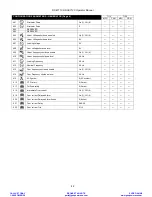
Page 37: ...RESERVED 108 Event log display format On 1 Off 0 109 Module powers up into AUTO mode On 1 Off 0 110 DTC string English only enable On 1 Off 0 X X CONFIGURATION PARAMETERS APPLICATION Page 2 7110 7120...

Page 38: ...y 316 Digital input C action if source user config 0 Action 317 Digital input C arming if source user config 0 Arming 318 Digital input C activation delay if source user config 0 00 319 Digital input...

Page 39: ...er config 0 00 338 Analogue input C sensor type 0 sensor type 339 Analogue input C sensor selection temperature sensor list 0 pressure temperature or percentage sensor 340 Analogue input C set as digi...

Page 40: ...larity 411 Digital output F source 0 Output source 412 Digital output F polarity 0 Output source Polarity 413 Digital output G source 0 Output source 414 Digital output Gpolarity 0 Output source Polar...

Page 41: ...00 507 Smoke limiting off 0 s 508 Safety On Delay 0 s 509 Warming up time 0 00 510 Return Delay 0 00 511 Cooling Time 0 00 512 ETS Solenoid Hold 0 00 513 Failed to stop delay 0 00 514 Generator trans...

Page 42: ...able On 1 Off 0 610 Under frequency shutdown level 0 0 Hz 611 Loading Frequency 0 0 Hz 612 Nominal Frequency 0 0 Hz 613 Over frequency shutdown enable On 1 Off 0 614 Over Frequency shutdown level 0 0...

Page 43: ...voltage return 0 V X X 709 Mains over Voltage trip level 0 V X X 710 Mains under frequency trip enable On 1 Off 0 X X 711 Mains under frequency trip level 0 0 Hz X X 712 Mains under frequency return...

Page 44: ...speed shutdown 0000 rpm 816 Over speed shutdown 0000 rpm 817 Low battery volts enable On 1 Off 0 818 Low battery volts warning 00 0 V 819 Low battery volts return 00 0 V 820 Low battery volts delay 0...

Page 45: ...14 CT Primary 0 Amps 915 Full load rating 0 Amps 916 Immediate Over current On 1 Off 0 917 Over current Delayed Alarm On 1 Off 0 918 Over current Delayed Alarm Action 0 Action 919 Over current Delay 0...

Page 46: ...igh alarm enable 0 0 00 bar 0 C 1005 Flexible sensor High alarm trip units depend upon sensor type 0 Action 1006 Flexible sensor Low warning enable 0 0 00 bar 0 C 1007 Flexible sensor Low warning trip...

Page 47: ...DSE7110 DSE7120 Operator Manual 47 1201 Time of day 0 00 1202 Day of week 0 Day 0 Monday CALL US TODAY 1 888 POWER 58 REQUEST A QUOTE parts genpowerusa com SHOP ONLINE www genpowerusa com...

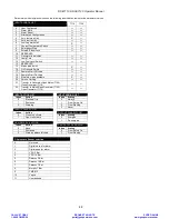
Page 48: ...Mains 7120 Close Generator 7110 22 Transfer to Mains Open Generator 7120 Open Generator 7110 INPUT ACTION LIST INPUT ARMING LIST Index Action Index Arming 0 Electrical Trip 0 Always 1 Shutdown 1 From...

Page 49: ...Cummins 8 PT100 9 Veglia 10 Beru 11 User defined Flexible sensor selections for Percentage type 0 Not used 1 Digital closed for alarm 2 Digital open for alarm 3 VDO Ohm range 10 180 4 VDO Tube 90 0 5...

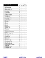
Page 50: ...y stop 30 Energise to stop 31 Fail to come to rest 32 Fail to start 33 Fuel relay 34 Gas choke on X X 35 Gas ignition X X 36 Generator Available 37 Generator over voltage shutdown 38 RESERVED 39 RESER...

Page 51: ...The engine should now run up to operating speed If not and an alarm is present check the alarm condition for validity then check input wiring The engine should continue to run for an indefinite period...

Page 52: ...nd wiring of fault indicated on LCD display Check configuration of input Fail to Start is activated after pre set number of attempts to start Check wiring of fuel solenoid Check fuel Check battery sup...

Page 53: ...ilable Check that the output configuration is correct to drive the load switch device and that all connections are correct Remember that the set will not take load in manual mode unless a remote start...

Page 54: ...ales department using the part numbers below 11 1 1 DSE7110 7110 terminal designation Plug description Part No 1 11 11 way 5 08mm 007 451 15 18 4 way 5 08mm 007 444 22 27 6 way 5 08mm 007 446 39 46 8...

Page 55: ...not fitted to DSE7120 controller NOTE Terminals 28 38 are not fitted to DSE7120 controller NOTE Terminals 66 69 are not fitted to DSE7110 controller 11 2 PURCHASING ADDITIONAL FIXING CLIPS FROM DSE I...

Page 56: ...rdous substances Lead Mercury Hexavalent Chromium Cadmium PBB PBDE s Exemption Note Category 9 Monitoring Control Instruments as defined in Annex 1B of the WEEE directive will be exempt from the RoHS...

Page 57: ...ly monitor and control the engine The industry standard communications interface CAN transports data gathered by the engine controller interface CAN This allows generator controllers such as the DSE 7...

Page 58: ...NTROLLER DIRECT CONNECTION To connect a 71xx series module to a PC the following items are required 71xx series module 71xx series configuration software Supplied on configuration suite software CD or...

Page 59: ...from its normal position drops fal ling at an angle 3 Protected against ingress of solid objects with a diameter of more than 2 5 mm Tools wires etc with a thickness of more than 2 5 mm are prevented...

Page 60: ...mited amounts of falling water and dirt 3 IP64 Provides a degree of protection against windblown dust rain and sleet undamaged by the formation of ice on the enclosure 3R IP32 Provides a degree of pro...

Page 61: ...Page Left Blank Intentionally DSE7110 DSE7120 Operator Manual ISSUE 3 CALL US TODAY 1 888 POWER 58 REQUEST A QUOTE parts genpowerusa com SHOP ONLINE www genpowerusa com...

Page 62: ...Page Left Blank Intentionally CALL US TODAY 1 888 POWER 58 REQUEST A QUOTE parts genpowerusa com SHOP ONLINE www genpowerusa com...

Reviews: