background image

Specifications 


29


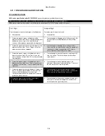
NEMA CLASSIFICATIONS


8600 series NEMA Rating (Approximate) 
 

12

 (Front of module when module is installed into the control panel with the optional sealing gasket).


2

 (front of module when module is installed into the control panel WITHOUT being sealed to the panel) 


NOTE: - There is no direct equivalence between IP / NEMA ratings. IP figures shown are approximate 

only. 


1


IP30


Provides a degree of protection against contact with the enclosure equipment and against a limited amount of  falling dirt.


2


IP31


Provides a degree of protection against limited amounts of falling water and dirt.


3


IP64


Provides a degree of protection against windblown dust, rain and sleet; undamaged by the formation of ice on the enclosure.


3R


IP32


Provides a degree of protection against rain and sleet:; undamaged by the formation of ice on the enclosure.


4 (X)


IP66


Provides a degree of protection against splashing water, windblown dust and rain, hose directed water; undamaged by the 
formation of ice on the enclosure. (Resist corrosion).


12/12K


IP65


Provides a degree of protection against dust, falling dirt and dripping non corrosive liquids.


13


IP65


Provides a degree of protection against dust and spraying of water, oil and non corrosive coolants.


Summary of Contents for DSE8660

Page 1: ...DSE8660 Operator Manual Issue 5 DEEP SEA ELECTRONICS PLC DSE8660 Operator Manual Document number 057 120 Author Anthony Manton...

Page 2: ...ctronics Plc at the address above The DSE logo is a UK registered trademark of Deep Sea Electronics PLC Any reference to trademarked product names used within this publication is owned by their respec...

Page 3: ...TERNET 19 3 8 DSENET FOR EXPANSION MODULES 22 3 9 SOUNDER 23 3 9 1 ADDING AN EXTERNAL SOUNDER TO THE APPLICATION 23 3 10 DIMENSIONS AND MOUNTING 24 3 10 1 DIMENSIONS 24 3 10 2 CABLE TIE FIXING POINTS...

Page 4: ...MODE 63 6 3 2 STARTING SEQUENCE 63 6 3 3 ENGINE RUNNING 64 6 3 3 1 BUS MODE 64 6 3 3 2 MAINS MODE 64 6 3 4 STOPPING SEQUENCE 64 6 4 MANUAL MODE 65 6 4 1 WAITING IN MANUAL MODE 65 6 4 2 ENGINE RUNNING...

Page 5: ...2 1 1 1 PACK OF PLUGS 80 12 1 1 2 INDIVIDUAL PLUGS 80 12 2 PURCHASING ADDITIONAL FIXING CLIPS FROM DSE 80 12 3 PURCHASING ADDITIONAL SEALING GASKET FROM DSE 80 12 4 EXPANSION MODULES 81 13 WARRANTY 82...

Page 6: ...157 Output Expansion Installation Instructions 1 2 TRAINING GUIDES Training Guides are produced to give handout sheets on specific subjects during training sessions DSE PART DESCRIPTION 056 005 Using...

Page 7: ...llers depending upon the status of the mains utility supply Synchronising and Load Sharing features are included within the controller along with the necessary protections for such a system This provi...

Page 8: ...us 60V protection for surges Reverse polarity protection 35V continuous Maximum operating current all inputs and outputs on 400mA at 24V 200mA at 12V Maximum standby current all inputs and outputs off...

Page 9: ...en 0 5VA 0 02 current shunts common mode offset 2V peak plant ground to CT common terminal Resolution 0 5 of 5A Accuracy 1 of Nominal 1A or 5A excluding CT error 3 5 INPUTS 3 5 1 DIGITAL INPUTS Number...

Page 10: ...he DSE8660 controller 3 6 2 OUTPUTS C D Type Voltage free relays fully configurable normally used for generator bus mains load switch control Rating 8A resistive 250 V AC 3 6 3 OUTPUTS E F G H I J Typ...

Page 11: ...0 baud subject to S W TX RX RTS CTS DSR DTR DCD Male 9 way D type connector Max distance 15m 50 feet RS485 Serial port Isolated Data connection 2 wire common Half Duplex Data direction control for Tra...

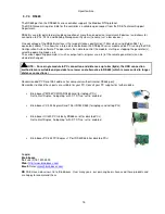
Page 12: ...tion suite software CD or available from www deepseaplc com USB cable Type A to Type B This is the same cable as often used between a PC and a USB printer DSE can supply this cable if required PC Conf...

Page 13: ...but can recommend PC add ons to provide the computer with an RS232 port Recommended PC Serial Port add ons for computers without internal RS232 port Remember to check these parts are suitable for your...

Page 14: ...020 245 NOTE For GSM modems a SIM card is required supplied by your GSM network provider For SMS only a normal voice SIM card is required This enables the controller to send SMS messages to designated...

Page 15: ...tc of the remote generator s can be viewed or changed NOTE For a single module to PC connection and distances up to 6m 8yds the USB connection method is more suitable and provides for a lower cost alt...

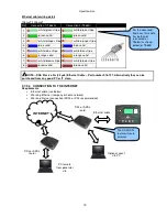
Page 16: ...t for connection to LAN local area networks Description 1 TX 2 TX 3 RX 4 Do not connect 5 Do not connect 6 RX 7 Do not connect 8 Do not connect 3 7 5 1 DIRECT PC CONNECTION Requirements DSE8660 Crosso...

Page 17: ...stripe white blue stripe 6 orange solid green solid 7 white brown stripe white brown stripe 8 brown solid brown solid NOTE This cable can be purchased from any good PC or IT store 3 7 5 2 CONNECTION T...

Page 18: ...e 8 brown solid brown solid NOTE DSE Stock a 2m 2 2yds Ethernet Cable Part number 016 137 Alternatively they can be purchased from any good PC or IT store 3 7 5 3 CONNECTION TO COMPANY INFRASTRUCTURE...

Page 19: ...d brown solid NOTE DSE Stock a 2m 2 2yds Ethernet Cable Part number 016 137 Alternatively they can be purchased from any good PC or IT store 3 7 5 4 CONNECTION TO THE INTERNET Requirements Ethernet ca...

Page 20: ...ite orange stripe 4 blue solid blue solid 5 white blue stripe white blue stripe 6 orange solid orange solid 7 white brown stripe white brown stripe 8 brown solid brown solid NOTE DSE Stock a 2m 2 2yds...

Page 21: ...all rule As the DSE8660 makes its user interface available to standard web browsers all communication uses the chosen port It is usual for a firewall to make the same port outgoing open for communicat...

Page 22: ...uivalent 600m 666 yds when using Belden 9271 or direct equivalent DSENet topology Daisy Chain Bus with no stubs spurs DSENet termination 120 Fitted internally to host controller Must be fitted externa...

Page 23: ...Configuration Suite PC software to configure an auxiliary output for Audible Alarm and by configuring an auxiliary input for Alarm Mute if required The audible alarm output activates and de activates...

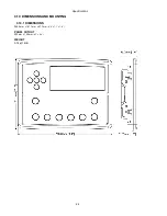
Page 24: ...Specifications 24 3 10 DIMENSIONS AND MOUNTING 3 10 1 DIMENSIONS 240 0mm x 181 1mm x 41 7mm 9 4 x 7 1 x 1 6 PANEL CUTOUT 220mm x 160mm 8 7 x 6 3 WEIGHT 0 7kg 1 4lb...

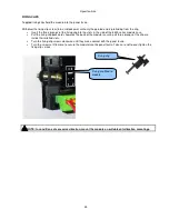
Page 25: ...ule case Pull the fixing clip backwards towards the back of the module ensuring all three prongs of the clip are inside their allotted slots Turn the fixing clip screws clockwise until they make conta...

Page 26: ...e taken not to overtighten the cable tie for instance with cable tie tools to prevent the risk of damage to the module case Cable tie fixing point With cable and tie in place 3 10 3 SILICON SEALING GA...

Page 27: ...talled into the control panel with the supplied sealing gasket 2 Front of module when installed into the control panel WITHOUT being sealed to the panel IEEE C37 2 Standard Electrical Power System Dev...

Page 28: ...enclosure is tilted at an angle up to 15 from its normal position drops falling at an angle 3 Protected against ingress of solid objects with a diameter of more than 2 5 mm Tools wires etc with a thi...

Page 29: ...rovides a degree of protection against limited amounts of falling water and dirt 3 IP64 Provides a degree of protection against windblown dust rain and sleet undamaged by the formation of ice on the e...

Page 30: ...nt and Output relays E F G H 3 Not Connected 4 Not Connected 5 Not Connected 6 Not Connected 7 Functional Earth 2 5mm AWG 13 Connect to a good clean earth point 8 Output relay E 1 0mm AWG 18 Plant Sup...

Page 31: ...85 approved cable MSC 31 MultiSet Comms MSC Link H 0 5mm AWG 20 Use only 120 RS485 approved cable 32 MultiSet Comms MSC Link L 0 5mm AWG 20 Use only 120 RS485 approved cable 33 MultiSet Comms MSC Link...

Page 32: ...pply AC Recommend 2A fuse 46 Mains Neutral N input 1 0mm AWG 18 Connect to Mains N incoming supply AC NOTE The above table describes connections to a three phase four wire system For alternative wirin...

Page 33: ...nts towards the MAINS p2 l or L is the primary of the CT that points towards the LOAD s1 is the secondary of the CT that connects to the DSE Module s input for the CT measuring I1 I2 I3 s2 is the seco...

Page 34: ...below If in doubt check with the CT supplier Pin No Description CABLE SIZE NOTES 56 CT Secondary for Load CT 2 5mm AWG 13 Connect to s1 secondary of Load CT 57 CT Secondary for Load CT 2 5mm AWG 13 Co...

Page 35: ...h to negative 70 Configurable digital input K 0 5mm AWG 20 Switch to negative 4 1 3 PC CONFIGURATION INTERFACE CONNECTOR DESCRIPTION CABLE SIZE NOTES Socket for connection to PC with 86xx series PC so...

Page 36: ...n using Belden 9841 or direct equivalent B SCR 4 1 5 RS232 CONNECTOR PIN No NOTES 1 Received Line Signal Detector Data Carrier Detect 2 Received Data 3 Transmit Data 4 Data Terminal Ready 5 Signal Gro...

Page 37: ...anufacturers and panel builders may use these diagrams as a starting point however you are referred to the completed system diagram provided by your system manufacturer for complete wiring detail Furt...

Page 38: ...Installation 38 4 2 1 3 PHASE 4 WIRE...

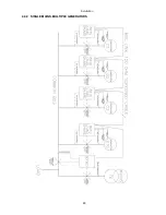
Page 39: ...Installation 39 4 2 2 SINGLE MAINS MULTIPLE GENERATORS...

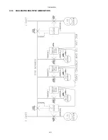
Page 40: ...Installation 40 4 2 3 DUAL MAINS MULTIPLE GENERATORS...

Page 41: ...Installation 41 4 2 4 MULTIPLE MAINS MULTIPLE GENERATORS...

Page 42: ...within the Specification section of this document and within the operator manual for the specific expansion module you are connecting to NOTE Screened 120 impedance cable specified for use with CAN m...

Page 43: ...t be followed Follow the typical wiring diagram as normal for all sections EXCEPT the earth points All points shown as Earth on the typical wiring diagram should connect to BATTERY NEGATIVE not earth...

Page 44: ...DSENet made up of the following devices Device Max number supported DSE2130 Input Expansion 4 DSE2131 Input Expansion 4 DSE2133 Input Expansion 4 DSE2152 Output Expansion 4 DSE2157 Output Expansion 10...

Page 45: ...AMF CONTROL MODULE Menu navigation buttons Four configurable LEDs Select Stop Mode Select Manual Mode Select Auto Mode Start engine s when in Manual or Test Mode Transfer to Bus Manual Mode only Trans...

Page 46: ...us LED On When The Bus Is On Load Bus Available LED On when the generator is within limits and able to take load Mains Available LED On when the mains is within limits and able to take load Close Main...

Page 47: ...to the module s operation 5 2 1 STARTING THE ENGINE S NOTE For further details see the section entitled OPERATION elsewhere in this manual Ensure all DSE8610 generator controllers are in the AUTO mode...

Page 48: ...STOPPING THE ENGINE S NOTE For further details see the section entitled OPERATION elsewhere in this manual With the DSE8610 s already in the AUTO mode select Stop Reset mode on all DSE8660 s in the s...

Page 49: ...e or by using the Front Panel Editor The screenshot shows the factory settings for the timers taken from the DSE Configuration Suite Software Alternatively to scroll manually through all instruments o...

Page 50: ...ents of this display may vary depending upon configuration by the generator manufacturer supplier The display above was achieved with the factory settings shown below in the DSE Configuration suite so...

Page 51: ...Volts L1 L2 L2 L3 L3 L1 Mains Hz Mains Amps Mains kW Mains kVA Mains pf Mains kVAr Mains kWh kVAh kVArh Mains configuration type Synchroscope Battery Voltage 5 3 3 BUS Bus volts L1 N L2 N L3 N Bus vo...

Page 52: ...s reset and reinitialised to ensure the modem does not hang up If the DSE86xx series module does not correctly communicate with the modem Modem initialising will appear on the Serial Port instrument s...

Page 53: ...oblems this information will aid troubleshooting Line Description RTS Request To Send Flow control CTS Clear To Send Flow control DSR Data Set Ready Ready to communicate DTR Data Terminal Ready Ready...

Page 54: ...seful troubleshooting tool In the case of GSM connection problems try calling the DATA number of the SIMCARD with an ordinary telephone There should be two rings followed by the modem answering the ca...

Page 55: ...if a modbus master PLC requests data from the DSE86xx modbus slave once per second the timeout should be set to at least 2 seconds The DSE Modbus Gencomm document containing register mappings inside t...

Page 56: ...isabled DHCP Disabled DHCP Disabled DHCP Disabled Net Net Net Network work work work Subnet mask Subnet mask Subnet mask Subnet mask 255 255 255 0 255 255 255 0 255 255 255 0 255 255 255 0 Network Net...

Page 57: ...til Ok to remove USB drive is displayed Data Logging Log to USB drive Logging active Ok to remove USB drive It is now safe to remove the USB drive This ensures the logging data file will save to memor...

Page 58: ...in the most recent shutdown alarms The module logs the alarm along with the date and time of the event If the module is configured and connected to send SMS text a text of the event is sent also To vi...

Page 59: ...oring of a digital input and indicating associated functioning user s equipment Such as Battery Charger On or Louver s Open etc WARNINGS Specific indication of a particular warning or condition backed...

Page 60: ...this manual Auto This button places the module into its Automatic mode This mode allows the module to control the function of the system automatically The module will monitor the remote start input a...

Page 61: ...e the load switch is closed CLOSE BUS This push button is used to control the closure of the bus load switching device and has two modes of operation 3 Synchronising is NOT enabled Pressing this butto...

Page 62: ...to your configuration source for the exact sequences and timers observed by any particular module in the field 6 1 ALTERNATIVE CONFIGURATIONS Depending upon the configuration of your system by the gen...

Page 63: ...ow the generator to operate fully automatically starting and stopping as required with no user intervention 6 3 1 WAITING IN AUTO MODE If a starting request is made the starting sequence will begin St...

Page 64: ...of active power kW to maintain the mains import export levels at the configured values This is configured into the Load parallel power parameter How much reactive power is taken from or exported to t...

Page 65: ...mits Activation of an auxiliary input that has been configured to remote start on load remote start in island mode or remote start off load Activation of an auxiliary input that has been configured to...

Page 66: ...his can be continuous parallel or island mode operation 6 5 1 WAITING IN TEST MODE When in test mode the set will not start automatically To begin the starting sequence press the button 6 5 2 ENGINE R...

Page 67: ...will remain without power Cease peak lopping and backup the failed mains supply NOTE At no time are the generators paralleled with more than one mains supply at a time Paralleling with mains supplies...

Page 68: ...junction with the CTs measuring the amount of load on the mains supply this CT allows the 8660 to determine what portion of the load is being supplied by the generators This allows the 8660 to remove...

Page 69: ...t appear on the LCD of the module as a text message However an output or LED indicator can be configured to draw the operator s attention to the event Example Input configured for indication The LCD t...

Page 70: ...latched will cause warning alarms to latch until reset manually This is enabled using the 8600 series configuration suite in conjunction with a compatible PC Display Reason BATTERY UNDER VOLTAGE The D...

Page 71: ...s pre V3 cannot communicate with modules V4 and onwards Use the DSE Configuration Suite Software to upgrade the firmware Tools Update Firmware of the older modules to V4 and onwards 7 4 ROCOF VECTOR S...

Page 72: ...T mode 8 1 2 MANUAL MODE Scheduled runs will not occur when the module is in MANUAL mode Activation of a Scheduled Run On Load when the module is operating OFF LOAD in Manual mode will have no effect...

Page 73: ...This configuration mode allows the operator limited customising of the way the module operates Use the module s navigation buttons to traverse the menu and make value changes to the parameters Previou...

Page 74: ...ber You can press left if you need to move back to adjust one of the previous digits When is pressed after editing the final PIN digit the PIN is checked for validity If the number is not correct you...

Page 75: ...are editing the value Press the up or down buttons to change the parameter to the required value Press to save the value The parameter ceases flashing to indicate that it has been saved To exit the ed...

Page 76: ...ency Trip 55Hz CT Primary 600A CT Secondary 5A Mains KW Rating 345kW Mains KVar Rating 258kW AC System 3 Phase 4 Wire Bus Start Delay On Load 5s Load Ramp Rate 3 s Insufficient Capacity Delay 1s Batte...

Page 77: ...r begins to flash to indicate that you are editing the value Press the up or down buttons to change the parameter to the required value Press to save the value The parameter ceases flashing to indicat...

Page 78: ...uccessful Synchronising 5 Place the 8660 module into STOP mode Place the 8610 s into AUTO mode Initiate a start by pressing the START button of the 8660 All 8610 s start upon receipt of the MSC start...

Page 79: ...tor be sure to press the Accept button to save the change before moving to another item or exiting the fascia editor Bus will not take load Ensure the generator available LED is lit Check that the out...

Page 80: ...Part Number DSE8610 057 513 DSE8660 007 514 12 1 1 2 INDIVIDUAL PLUGS 8600 series terminal designation Plug description Part No 1 11 11 way 5 08mm 007 451 15 19 Not fitted to DSE8660 22 30 9 way 5 08...

Page 81: ...ic input expansion module provides additional resistive digital voltage 0 10 V and current 4 20 mA inputs for use with the controller 2131 001 00 055 115 057 139 053 125 4 Model DSE2133 RTD Thermocoup...

Page 82: ...e 2002 95 EC 2006 To remove specified hazardous substances Lead Mercury Hexavalent Chromium Cadmium PBB PBDE s Exemption Note Category 9 Monitoring Control Instruments as defined in Annex 1B of the WE...

Page 83: ...This page is intentionally left blank 83...

Page 84: ...This page is intentionally left blank 84...

Reviews: