background image


21 | 

P a g e


014010-001 Rev 01 

©2019 Data Sciences International.


4)


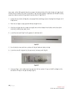
Feed the removal tool into the internal bore of the cartridge, and pry part of the O-ring out of its seating 
groove. Grab the O-ring with a pair of tweezers and completely remove it. Please note that there are two 
internal O-rings in each cartridge. 

 
5)


Inspect all O-rings for the following defects: 


Visual defects

such as cracking or distortion. 


Brittleness or lack of flexibility. 
 

Discard all rings that display any of the above symptoms. 

 
6)


Place any rings that pass inspection into a beaker of isopropyl alcohol (IPA), add the two cartridges, and soak 
these components overnight. This will ensure that the seating grooves on the cartridges as well as the old 
rings are thoroughly clean before being re-installed. 

 
7)


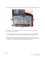
After soaking overnight, use the bore brush (Fig 21) to clean the inner bore and O-ring grooves and briefly dip 
them back into the IPA. Remove all components (cartridges, O-rings) from the IPA and dry them with a paper 
towel. 

 
8)


Using your fingers, install (cleaned or new) O-rings in the external seating grooves on the cartridges. 

 
9)


Please note that installing (cleaned or new) O-rings in the internal seating grooves of the cartridge is more 
difficult. The best way to do this is as follows: 
 
a)


Using your fingers, bend the O-ring into an oval and push it into the bore. 
 

b)


Take a small screwdriver (after checking to make sure the blade doesn’t have any sharp edges that could 

damage the O-ring) and push the ring until part of it makes contact and slips into the seating groove. 
 

c)


Starting from the point where the ring is already seated, carefully work the remainder of the O-ring into 
the seating groove. 
 

d)


This is important!

 Double-check that both rings are properly seated (by gently prodding the entire 

circumference with the screwdriver) before moving on to the next step. 


10)


Reinsert the cartridges into the generator, and re-install the three retaining screws, which should be hand 

tightened. If the screw holes won’t align, the cartridge is in the wrong hole.


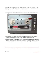
BRUSHING THE INSIDE OF THE TRANSVERSE LUNG PIPE  


Every month or after 800 cigarettes have been smoked, brush out the inside of the transverse lung pipe to remove 
any accumulated tar. The Individual Cigarette Puff Generator must be powered down before you attempt to access 

Summary of Contents for Individual Cigarette Puff

Page 1: ...highlights how DSI s Individual Cigarette Puff Generator 601 2055 001 can be used to automate the smoking of cigarettes or electronic cigarettes to capture direct smoke with the purpose of exposing co...

Page 2: ...Regular Cigarette Holder 9 Operation 12 Period 12 Puffs min 12 Volume 12 Recommended Ranges 13 Cigarette Time 14 Smoke Pump 14 eCigarette mode 14 Service Mode 15 System Operation 15 Operational Steps...

Page 3: ...3 P a g e 014010 001 Rev 01 2019 Data Sciences International Parts List 24 Replacing the Lung 24 Technical Support 29 Appendix 30 Dimensions 30 WELCOME...

Page 4: ...external port The major components include An Inhale Adapter where cigarette holders are inserted Figure 1 Various holders to connect different types of regular or electronic cigarettes A pump assemb...

Page 5: ...ocument does not include details on how to connect the individual Cigarette Puff Generator to any specific apparatus PHYSICAL HARDWARE Figure 1 The left side of the unit can be seen in Figure 2 This s...

Page 6: ...it is secure Connect a tube from the Direct Smoke port to the exposure chamber The Individual Cigarette Puff Generator is now set up and ready to use LOADING CIGARETTES The Individual Cigarette Puff...

Page 7: ...is manual Fig 4 Side View Front View Figure 4 A duckbill valve should be connected to the back of this holder before connecting it to the Individual Cigarette Puff Generator Fig 5 The purpose of this...

Page 8: ...ndicate that the duckbill valve is stuck closed Check the valve and clean or replace as needed Once the duckbill valve is firmly seated on the back of the holder it can be plugged in to the adapter on...

Page 9: ...then be inserted into the holder Fig 8 Figure 8 REGULAR CIGARETTE HOLDER This holder is designed to accept the shape of a Kentucky 3R4F Reference Cigarette though any cigarette with the same diameter...

Page 10: ...10 P a g e 014010 001 Rev 01 2019 Data Sciences International Figure 9 The cigarette can then be inserted into the holder Fig 10 Figure 10...

Page 11: ...the sounds of the unit the lighter can be held to the tip of the cigarette for several seconds starting with this pause so the draw period ignites the tobacco within the cigarette tip INDIRECT SMOKE...

Page 12: ...o choose the desired setting and press OK PUFFS MIN The Puffs min setting determines the frequency of draw cycles This can be set from 1 to 5 puffs minute in 1 puff minute increments Fig 13 Example A...

Page 13: ...per combination has been selected the following error screen will be displayed Fig 15 Figure 15 Press OK and adjust one or more settings to build a recommended combination WARNING Operating outside th...

Page 14: ...OK Note This setting can be changed on the fly While the ember unit is smoking cigarettes the time remaining will periodically be displayed on the screen Pressing up down will add subtract 15 seconds...

Page 15: ...is an essential maintenance focus All flow paths will collect tar and should be serviced as needed This section explains how to properly maintain your DSI Individual Cigarette Puff Generator and keep...

Page 16: ...equently Description of Required Routine Maintenance Daily Every week or 200 cigarettes Every two weeks or 400 cigarettes Every month or 800 cigarettes Clean cartridges with isopropyl alcohol IPA X Br...

Page 17: ...20 that attach each cartridge to the generator Figure 20 3 Pull the cartridges out of the generator and place them in a glass container with enough isopropyl alcohol IPA to completely submerge the car...

Page 18: ...artridges out of the generator 2 Place the cartridges in isopropyl alcohol IPA overnight to soak 3 After the cartridges have been soaked overnight remove the cartridges from the IPA and dry them both...

Page 19: ...nd right cartridge Note that there are two internal O rings in each cartridge and both should be lightly lubricated Fig 24 Figure 24 9 Reinsert the cartridges into the generator and re install the thr...

Page 20: ...s with any of the above indications should be replaced using a new ring from the generator s maintenance kit Rings with no defects may be reused 1 Remove the two direct smoke cartridges by unscrewing...

Page 21: ...n the external seating grooves on the cartridges 9 Please note that installing cleaned or new O rings in the internal seating grooves of the cartridge is more difficult The best way to do this is as f...

Page 22: ...enu Fig 27 Figure 27 2 Press the OK button This moves the lung s actuators into a safe position for cleaning the transverse lung pipe 3 Power down the generator by turning its main power switch to OFF...

Page 23: ...in Figure 29 below Pull slowly and firmly Do not tug on the attachment plate if you do you risk damaging the wiring Do not remove the attachment plate more than one half inch from the generator Figure...

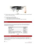
Page 24: ...these parts in stock so none of your critical experiments are compromised for lack of a needed part Description of Part Part Number Inner O rings 009450 001 Outer O rings 009460 001 Tube of O ring gr...

Page 25: ...nu Fig 33 Figure 33 2 Press the OK button This moves the lung s actuators into a safe position for removing the lung 3 Power down the Individual Cigarette Puff Generator by turning its main power swit...

Page 26: ...26 P a g e 014010 001 Rev 01 2019 Data Sciences International 5 Disconnect the blue tube that connects from the cigarette adapter to the Inhalation actuator Fig 35 Figure 35...

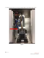
Page 27: ...27 P a g e 014010 001 Rev 01 2019 Data Sciences International 6 Disconnect the connections for the Lung and the Inhalation and Exhalation actuators from the motherboard Fig 36 Figure 36...

Page 28: ...e unit 9 The replacement lung can be inserted and the new connections outlined in steps 5 6 above can be made NOTE The Exhalation actuator is the one that is in line with the Direct Smoke port on the...

Page 29: ...please feel free to contact us We are happy to help DSI TECHNICAL SUPPORT NORTH AMERICA Email Support datasci com Toll free in U S and Canada Phone 1 800 262 9687 Monday through Friday 8 AM to 5 PM CS...

Page 30: ...30 P a g e 014010 001 Rev 01 2019 Data Sciences International APPENDIX DIMENSIONS...

Reviews: