9
Figure1 XDS560v2 Emulator
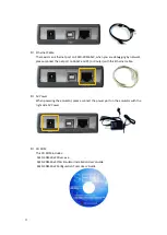
Ethernet port, USB interface and power interface on one side of the Emulator
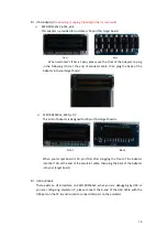
Six LED indicators on SEED-XDS560v2 : COM-LED1, COM-LED2, COM-LED3, EMU-LED1,
EMU-LED2, EMU-LED3 (from left to right)
Table1 LED Information
LED
Color
Description
COM-LED1
Red
XDS560v2 Ready
COM-LED2
Red
Shows XDS560v2 FPGA programmed state
COM-LED3
Green
Shows XDS560v2 system Boot Activity
EMU-LED1
Green
Shows target to XDS560v2 Trace Activity
EMU-LED2
Red
Shows XDS560v2 to host Activity
EMU-LED3
Green
Show connectivity via CCS when at on a state
Summary of Contents for SEED-XDS560v2
Page 1: ...SEED XDS560v2 JTAG Emulator User s Guide 2011 05 DSP Development Systems ...
Page 2: ...SEED XDS560v2 JTAG Emulator Installation User s Guide http www seeddsp com Version A 2011 7 ...
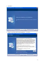
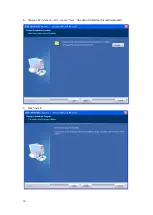
Page 15: ...14 2 Click Next 3 Choose I access the terms of the license agreement click Next ...
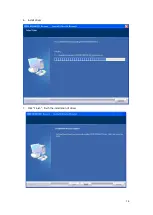
Page 17: ...16 6 Install driver 7 Click Finish finish the installation of driver ...
Page 30: ...29 Appendix A JTAG Adaptor Introduction A 1 SEED XDS560v2_6014_v0 3 ...


