10
4.1 Standard configuration
4.1.1 Rotor motor
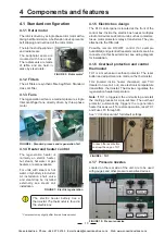
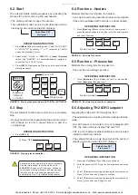
The rotor is driven by a single phase rotor motor with a
timing belt transmission. A belt tension device prevents
belt slipping and overload of the rotor motor.
The rotor has both peripheral
and radial seals.
The peripheral seals are
mounted with hose clips.
The radial seals are made
of teflon and are held in
place by steel rulers.
4.1.2 Filters
The air filters are synthetic fibre bag filters. Standard
class G4 filter.
4.1.3 Fans
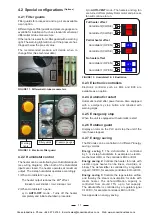
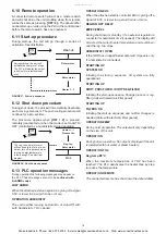
The regeneration air fan is a medium pressure, single
inlet centrifugal fans, directly driven by three-phase
motor.
4.1.4 Heater and heater control
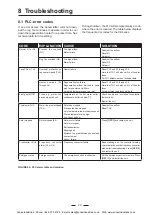
The regeneration heater is
normally an electric heater,
but steam, hot water or gas
heaters are also available.
For units with steam or hot
water, only battery is included.
At installation shall valve
and steamtrap be installed
externally, see steam coil
installation.
* Components may slightly differ from delivered product
4 Components and features
FIGURE 5: Rotor motor*
FIGURE 6: Standard process and regeneration fan*
FIGURE 7: Electric regeneration
FIGURE 9: TH1
Process
Reg
Process
Reg
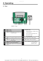
FIGURE 10: Pressure nozzles
4.1.5 Electric box design
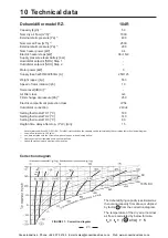
The PLC control panel is located at the front of the
control box. Inside, the electric box houses multiples
electronic devices and control units, such as contactors,
fuses, motor protectors, relays, transformer. They are
attached to the DIN-rails
Possible remote ON/OFF control (for example
humidistat) and potential free alarm contacts are to be
connected on this fixed terminal, see wiring diagram
for installation.
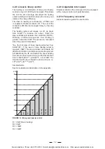
4.1.6 Overheat protection and control
thermostat
TH1 is a mechanical overheat protector. The reset
button and adjustment are made on the thermostat.
TH2 (located inside heater champber) and TH3
(located on wet air out) are electronic temperature
transmitters, thermostat. The devices regulates the
regeneration heater temperature.
Note:
If TH1 is triggered, the unit will stop and start
the cooling process for a pre-set time. The overheat
protector automatically triggers the regeneration
heater fuses as well. To restore operation, reset TH1
and Fuses F3 through F6.
See
“10 Technical data”
for default settings.
4.1.7 Pressure nozzles
Located on the rear side of the unit. Are to be used
with gauges and other pressure sensitive devices.
The electric heater battery has a
thermostat. The thermostat is found in
the electric box.
FIGURE 8: Inside electric cabinet
To reach the reset button,
unscrew the cap on TH1
counter-clockwise.
Cooke Industries - Phone: +64 9 579 2185 Email: sales@cookeindustries.co.nz Web: www.cookeindustries.co.nz


