background image

20

CODE

EXPLANATION CAUSE

SOLUTION

Motorst. Q1 or Q2.

Process  fan  overload 
(Q1).

Too high airflow.
Motor failure.

Readjust the airflow.
Reset Q1.
Set point.

Reg. fan overload (Q2).

Too high airflow.
Motor failure.

Readjust the airflow.
Reset Q2.
Set point.

Fuse F3-6 or TH1.

Overheat  protection  on 
reg heater tripped  (TH1).

Heater failure.

Reset TH1 and F3 through F5.
Note  that  TH1  will  also  switch  off  heater 
fuses.
For TH1 adjustment see technical data.

Heater  overload    (F3 
through F6).

Regeneration fan failure.
Regeneration  airflow  blocked  in  some 
way, for example dirty filters.
Very high temperature on reg. inlet.

Reset TH1 and F3 through F5.
Note  that  TH1  will  also  switch  off  heater 
fuses.
For adjustment see technical data.

Frost guard GT81

Freezing  protection 

device stops the unit.

Temperature  on  the  hot  water  outlet  /

condensate outlet is below 7°C.

Check  supply  and  insulation  for  potential  

thermal loss.

Restart the unit.

Thermostat TH3.

Wet air thermostat tripped 
(TH3).

Rotor has stopped.
Process fan has stopped.
Very low moisture load in the process air.
Wet air temperature too high.
Low react. air flow.

Readjust the airflow.
Reset TH3.

Rotor stopped.

Rotor stopped (E2).

Rotor motor failure.
Rotor motor gear.
Belt transmission.
Slipping belt.
Distance too great between sensor and 
contact screw.
Sensor failure.

Press 

[OFF/1]

 and restart the unit.

Fr.converter U1/U2. Frequency  converter 

alarm (U1 or U2).

Frequency converter failure.

Read  message  on  the  converter  display, 
check the list/check the frequency converter 
manual for troubleshooting. Press 

[OFF / 2] 

and restart the unit.

Emergency stop.

Emergency stop.

The emergency button is still active.

Pull the emergency button to restore. Press 

[OFF / 1]

 and restart the unit.

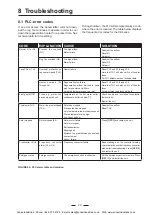
FIGURE 29:  PLC alarm table and solution

8  Troubleshooting

8.1  PLC-error codes

If  an  error  occurs,  the  dehumidifier  will  shut  down, 

but the reg. fan continues to operate in order to cool 

down the regeneration heater for a preset time. See 

technical data for time setting.

During shutdown, the PLC will promptly display a code, 

where the error is located. The table below displays 

the frequent error codes for the CZ-series.

Cooke Industries - Phone: +64 9 579 2185    Email: sales@cookeindustries.co.nz    Web: www.cookeindustries.co.nz

Summary of Contents for RECUSORB RZ-104R

Page 1: ...signal from external regulator The product picture may differ from the actual product INSTRUCTION MANUAL Document version EN 08 11 05 Product RZ 104Rsp Order 110 231 Cooke Industries Phone 64 9 579 21...

Page 2: ...Cooke Industries Phone 64 9 579 2185 Email sales cookeindustries co nz Web www cookeindustries co nz...

Page 3: ...Electronic controllers 11 4 2 4 Automatic restart 11 4 2 5 Emergency stop 11 4 2 6 Rotation guard 11 4 2 7 Energy saving 11 4 2 8 Linear binary control 12 4 2 9 Adjustable rotor speed 12 4 2 10 Frequ...

Page 4: ...design 9 FIGURE 6 Standard process and regeneration fan 10 FIGURE 7 Electric regeneration Heater 10 FIGURE 5 Rotor motor 10 FIGURE 8 Inside electric cabinet 10 FIGURE 10 Pressure nozzles 10 FIGURE 9...

Page 5: ...installation operation and maintenance of the equipment supplied 1 4 2 Intended use Thisequipmentisspecificallydesignedforatmospheric air drying It is unsuitable for any other use For further advice...

Page 6: ...electrical protection and alarm circuits must not be modified or adjusted Factory default parameters are shown in the electrical wiring diagrams Attention Safety functions The operation of all electr...

Page 7: ...s not protected within a weatherproof enclosure Is not operated within the permitted operating parameters see technical specifications Is operated outside the scope of normal use see intended use 1 4...

Page 8: ...well proven air drying technology using the adsorption principle provides great flexibility in solving humidity problems It offers the user independent humidity control down to dew points far lower t...

Page 9: ...The regeneration fan removes residual heat from the regeneration heater for ten minutes after the unit has been switched off The access panel at the front of the unit can easily be opened to enable se...

Page 10: ...at the front of the control box Inside the electric box houses multiples electronicdevicesandcontrolunits suchascontactors fuses motor protectors relays transformer They are attached to the DIN rails...

Page 11: ...d with a emergency stop button and labelled with warning signs 4 2 5 Emergency stop When the unit is equipped with automatic restart 4 2 6 Rotation guard Display an larm on the PLC and stop the unit i...

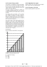
Page 12: ...eating streches from 0 8kW R1 If the need of more heating output is required 8kW The step controller will activate R2 8kW with full effect and at the same time the program will deactivate the R1 and r...

Page 13: ...the lowest set point is connected to humidistat 1 see enclosed wiring diagram This will switch off the whole heater regen fan and if auto off is chosen process fan and rotor motor In auto vent mode th...

Page 14: ...the inspection doors should be as wide as the unit itself For more detailed information on working space and foot bolt hole dimensions see appendix The standard unit is designed for indoor installati...

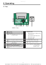
Page 15: ...Selecting the active heater steps for electric heater 4 Temp 7 Temperature setting for TH2 and TH3 10 Select choice confirm choice 5 Mode 8 Select different mode AUTO OFF or AUTO VENT 11 i Display fi...

Page 16: ...key again to view the rest of the heater groups and to exit the menu ON OFF Heater Temp Mode Info Hour Hour proc reg 9 0 8 7 4 5 6 3 2 1 1 Select run time 1 FIGURE 21 Run time for heaters 6 5 Run time...

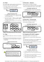
Page 17: ...s Mode 8 to enter dehumidification mode Select AUTO VENT or AUTO OFF by entering 1 or 0 respectively Confirm and exit by pressing twice 3 Select REMOTE or LOCAL on Local Remote switch 4 Press ON 1 Dis...

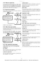
Page 18: ...LC These messages are not to be confused with ALARMS codes LOW HUMID When the attached external regulator is giving off a signal 0 5V or lower in a period 5 mins or more OPERATION HUMIDISTAT The unit...

Page 19: ...ON and then switch it OFF watching as the fans slows down the direction of fan rotation If incorrect check troubleshooting 3 Balance the airflows using the dampers in the duct work For maximum dehumi...

Page 20: ...w moisture load in the process air Wet air temperature too high Low react air flow Readjust the airflow Reset TH3 Rotor stopped Rotor stopped E2 Rotor motor failure Rotor motor gear Belt transmission...

Page 21: ...hot 30 60 C If the unit does not maintain the required humidity look for the following causes 8 3 Capacity Test Ifnofaultcanbefoundaftercheckingastroubleshooting table a performance test should be ca...

Page 22: ...below shall however be noted 1 Let the dehumidifier be shut off for at least an hour 2 Carefully remove the rotor from the unit The rotor is removed in the following way a Open the lower door s and re...

Page 23: ...80 553 Speed of rotor rotation rph 46 49 10 Noice level dB A 4 91 Air filter class G4 G4 G4 Filter change at pressure Pa 5 250 250 250 Electric compartment protection class IP54 IP54 IP54 Humidistat c...

Reviews: