21
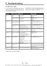
PROBLEM
CAUSE
SOLUTION
The unit does not maintain the
desired %RH humidity despite
operating at full capacity.
Dehumidification capacity is
insufficient although both dry
and wet air ducts are warm
Check the real moisture load and compare to design data. The unit
may be too small.
Check the airflow volumes, filter and adjustment of dampers.
Check the rotor for correct position and alignment to its panel, and
ensure that there are no leakages.
Both air ducts are cold
Is the unit switched on?
Is any of the motor protections alerted?
Check that the wet air damper is not closed.
Check the regeneration filter.
Check operation of the regeneration fan.
Dry air duct is cold and wet air
duct is very hot
Check rotation of the rotor.
Check process air fan.
Check that the dry air damper is not closed.
Check the process air filter.
The process fan and/or reg. fan is
spinning in the opposite direction
The incoming phase supply
wiring is incorrect
Switch the main switch to "0" and switch off incoming voltage. Change
over two of the three incoming phase supply wires.
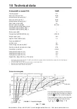
FIGURE 30: Troubleshooting and solution table
8.2 Capacity troubleshooting
The dehumidifier performance can be checked very simply by feeling the temperature of the uninsulated duct-
work near the unit.
Normally with the unit working at nominal conditions (with process air at room temperature), the dry air duct
should be warm (25-40°C) and the wet air duct should be warm or hot (30-60°C).
If the unit does not maintain the required humidity look for the following causes:
8.3 Capacity Test
If no fault can be found after checking as troubleshooting
table, a performance test should be carried out on the
dehumidifier, proceeding as follows.
1. The different moisture contents x (g/kg), in the
four airflows, can be determined by using wet
and dry thermometers. To receive the moisture
contents the measured temperatures shall be
plotted in a psychometric chart.
Process air in: x
PI
Process air out: x
PO
Regeneration air in: x
RI
Wet air out: x
RO
2. Calculate from the actual temperatures the
density of the two outlet airflows D
PO
(kg/m
3
)
and D
RO
.
3. Measure the dynamic pressure
∆
p (Pa) in the
air ducts, by using a Prandtl tube. The dynamic
pressure is measured by the difference between
the total pressure and static pressure in the duct.
Measurements shall be done in a straight
part of the duct-work. In order to avoid faulty
measurements caused by turbulent flows,
measurements should not be done close after
a bend or a fan.
The flow rate in each duct can be calculated as:
w = ( 2 *
∆
p / D )
1/2
(m/s)
Where D is the densities according to item 2.
Then calculate the volume air flows, V
PO
(m
3
/h)
for the dry air and V
RO
for the wet air:
V = w * A * 3600 (m
3
/h)
Where A is the cross section area of each duct.
Now determine the de-humidification capacity,
Q (kg/h), by the following equation.
Q = ( Q
P
+ Q
R
) / 2 (kg/h)
where
Q
P
= V
PO
* D
PO
* ( x
PI
- x
PO
) / 1000
and
Q
R
= V
RO
* D
RO
* ( x
RO
-x
RI
) / 1000
Compare this measured capacity to the capacity
which can be calculated from the data sheet.
Cooke Industries - Phone: +64 9 579 2185 Email: sales@cookeindustries.co.nz Web: www.cookeindustries.co.nz

